Adding payload release to a Bugs 3 Pro

Drones are perfect for hanging up antenna wires in trees. Just hang a small weight connected to a fishing line, drop it where you want it and use the fishing line to haul something heavier up.

The problem is getting a cheap drone that can do the job.

I ordered a very cheap Bugs 3. This one do have an internal camera connector with three pins. One of them changes state when you press the camera button on the remote. Perfect, I thought. The problem was the Bugs 3 is not very easy to precision fly as it has no altitude control.

So, on to the next one, a Bugs 3 Pro. This has both altitude control and headless mode flight. A bit more expensive but SO much more controllable. The problem was there was no internal camera connector. There was an empty connector but that seems to be related to the position leds or something. So, what to do…?

There actually was a camera supplied with the Bugs 3 Pro. USB connected, it seemed. But at a closer inspection… The camera is just ordered to take pictures or shoot video. This is put on the SD card inserted in the camera or sent to your mobile using wifi. So, is it really running USB…? Isn’t the USB stack (plus hardware) a bit hefty to put on a drone controller just for the camera?

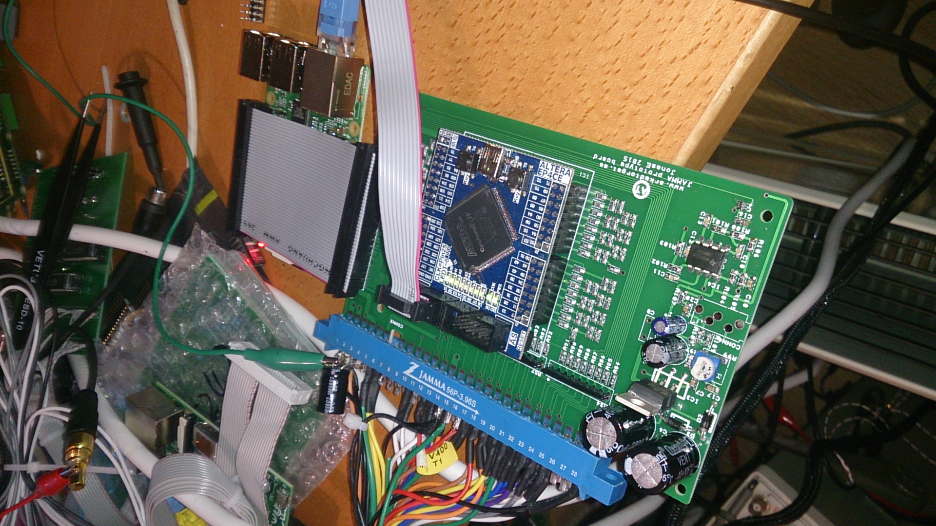
I hooked up my oscilloscope and apart from +5V and 0V there was some UART communication on one of the wires. 38400 baud. And when I pressed the camera button I got a small data package on the serial line. I hooked it up to an Arduino, no interface HW needed…

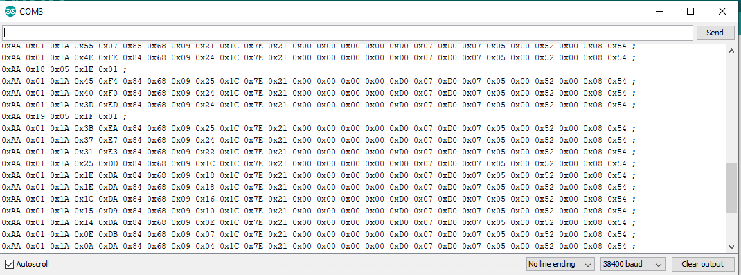
See those short packets? These are the photo packets… Now we just have to catch them.

This Arduino code, compiled for a Nano, will listen for the short and long camera key press data packages and control a RC servo connected to pin A0. From the “USB” connector cable I use the 5V (red) connected to 5V on the Nano and 0V (black) connected to 0V on the Nano. The serial port from the “USB” connector (in my case this cable was green, I don’t know if this is standard) can be connected directly to the “RX” pin of the Arduino. You cannot update the Nano with new software while having the drone connected.

The power for the RC servo I stole from the drone battery. I used 3 diodes in series, 1N4007. Type is not critical but it should take some current (1A in my case) and the voltage should be dropped from 7.2 to around 5V for the servo to be happy.

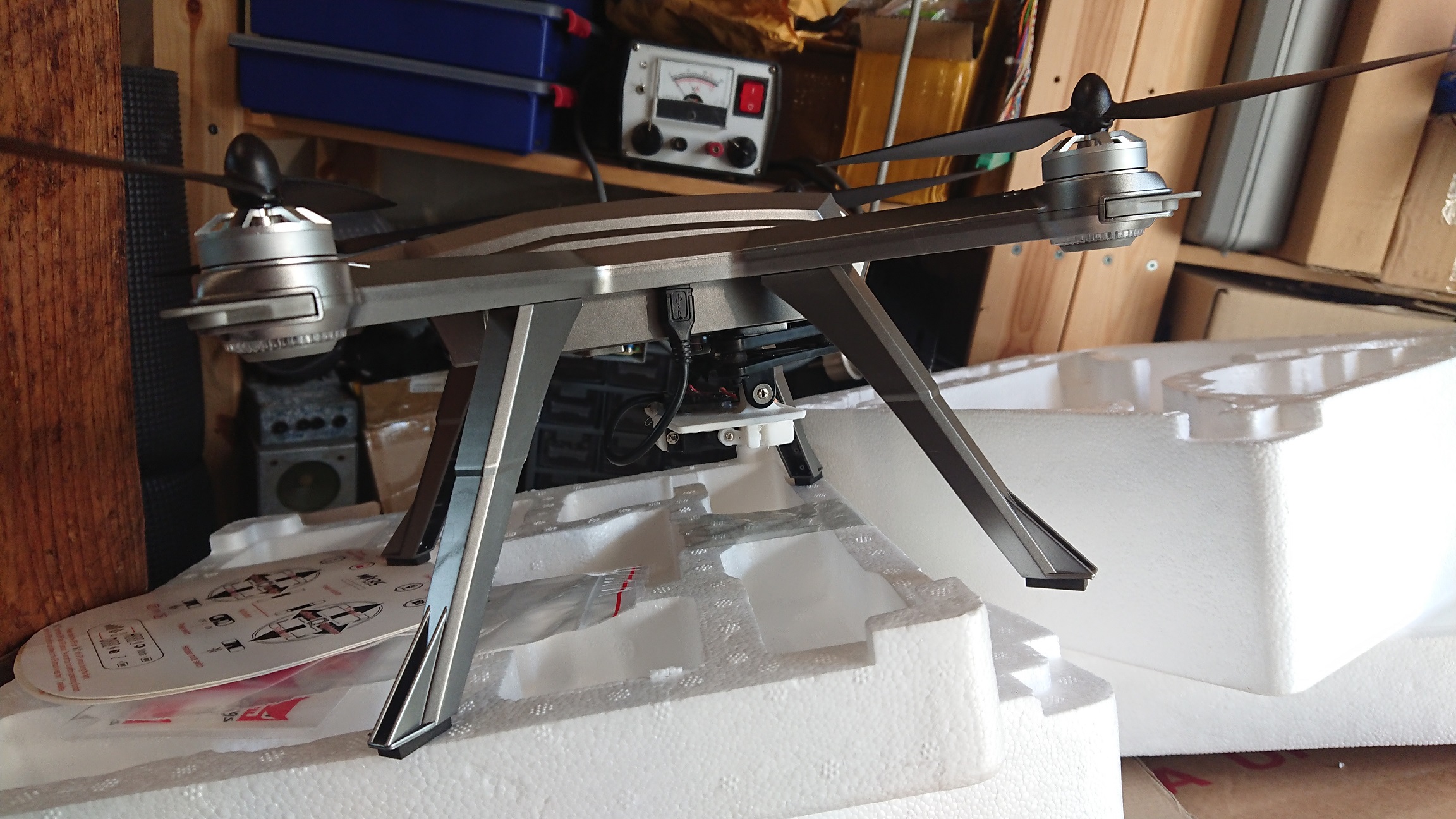
Ok, servo working fine attached to the Arduino and drone… Now we need some mounting stuff for it all. I threw this together for testing.

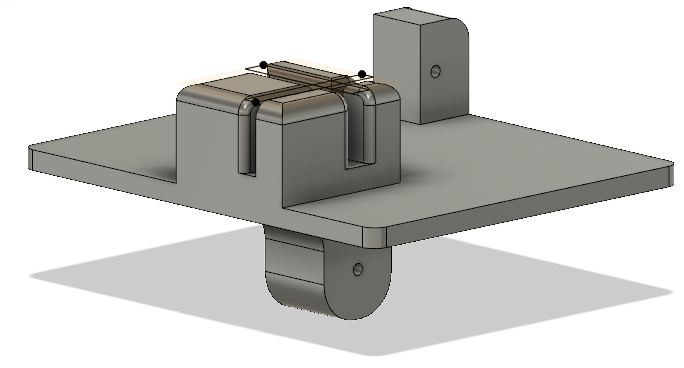
The bottom fits the camera mount supplied with the Bugs 3 Pro. A little hard to 3D-print but it works…

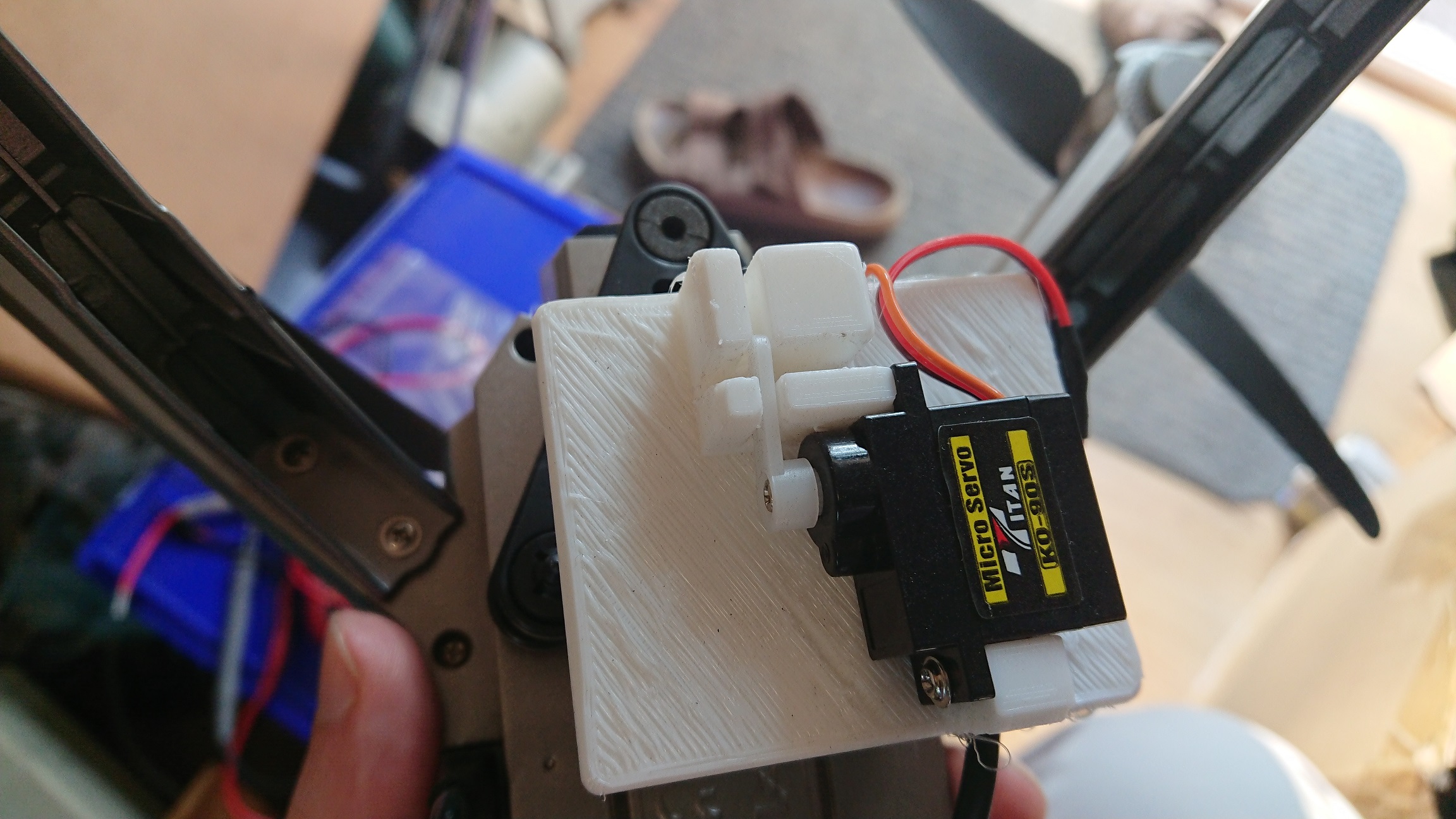
Here is the STL for the servo holder.

Stuff you need (apart from tools):
Arduino Nano with developing tools
3D printed servo holder
USB cable to cut
Micro RC servo


Tandberg series 15

This is a very common player in Sweden since there seems to have been one in every classroom in Sweden up to the mid 90’s or so. Not all are in this condition though, even if they are built like tanks. 🙂

I got this from a radio amateur friend. He said it didn’t work, and it didn’t. Mechanically it was fine but there were just strange noises when I tried playback. Actually, very interesting noises… Everything from blowing wind to someone whispering something to heavy oscillations with varying frequencies. I though there was a bad capacitor or transistor somewhere but it turned out to be the rec/playback switch. These are open in these and all it needed was some gentle cleaning. Then it sprung to life and hasn’t acted up since (tested it for many hours now). These are very stable machines.

Tape recorders

Ok. I have this thing for open reel recorders. I have had it all my life, since I found my mothers Grundig in my grandmothers attic. I must have been 4 or 5 and was totally amazed.

Today I have quite a few. Actually I don’t really keep track, but probably less than 15. 🙂 They are ranging from the early Philips ones listed here through the Tandberg ones used at schools here in Sweden up to my Revox A77 and Tandberg 9100X. Both the Revox and the Tandberg will have their own sections here soon, they both need work. The Tandberg has a near-deaf output channel and the Revox has a near-deaf input channel. I just got the pinch-roller for the Tandberg rebuilt (it started to turn to goo) and at that point I realized the Revox probably was next so I got a repro pinch-roller for it as a spare.

My Eben

DSC_0124I got this one when I was a kid. I loved it and played it from dusk til dawn. 🙂

It did have some problems with speed now and then but otherwise it was surprisingly good, and sounds better than many recorders from the same era. This was probably a low-cost machine. It is very light, it is battery operated and it runs at 9.5cm/s. It has no real flywheel, the capstan is driven by a light wheel rim-driven by the motor. This actually works well. 🙂

DSC_0125I got this one with it and I thought until now that it was a Luxor recorder, but it is not. I have yet to find out why they used a Luxor power adapter. Was this original or did someone patch them together before I got it?

It did have some problems. First I disconnected the speaker cables at some point and without any clue or a schematic it was not that obvious… But I got it sorted.

Another problem is the capstan and the pinch roller. The capstan was out of alignment and the pinch roller pin was bent. Getting this to work 100% is not easy. It would be much better to have some tool to at least set one of them correct… Now there are at least 4 variables. 🙂 I got it working well enough for now.

Another problem is the speed… I would like to turn it up a few %. There is a pot on the motor PCB but that does not seem to do anything useful. 🙂

If someone happens to have the service manual I would be very grateful.


My EL3586

DSC_0117I bought this one from a audio-dealing friend and I knew it needed work. It needed a new re-wind belt (old one turned into goo) and some O-rings to replace the rubber on some wheels for fast forward and re-wind. It looks a lot like the 3585 but it has some enhancements like an idler wheel between the motor and capstan wheel and a tone control. Once I got the mech running smoothly it actually sounds nice! Not much hi-end (it is limited to 8.5kHz) but it still is nice to listen at.

This one is actually done at the moment… I think it works just as it should. 🙂

My EL3585

DSC_0130This is my EL3585. I found it at a flee market for motor hobbyists and the recorder was in a really bad shape. At first I just went by thinking it was “too dead for resurrection” but I couldn’t help myself. It turned out it was not that bad. Some bad solder joints on the PCB, some rubber was transformed to goo (easily replaced by O-rings) and all it really needed was a new belt for the re-wind.

I’m not very pleased with the sound, though. It sounds like it has a peak at 2kHz or something and if I record something with it it sounds even worse. The problem is I’m not sure if it is anything wrong with it or not. I even replaced all caps and it sounded exactly the same.

DSC_0116

This is an early machine running at 4.75cm/s and the manual says it goes up to 5.5kHz which is not much. Just a little better than the old fashion telephone. Recorded speech sounds more than ok. It also shows some ringing in the amplifier… It goes away when I replace the speaker with a resistor, though. It would be great to get hold of another one to compare with.

The two top pieces are missing as well as the battery piece and the handle. Half of the microphone was included. 🙂 I will print the missing pieces when I get time.

My EL3510

2017-11-07 20.40.37Here it is. It found it at a flea market for audio hobbyists.

It looked awful. Love at first sight! 🙂

First step was to tear it down (which was a small adventure in itself), replace all electrolytic caps and the other caps as well. Then I had to replace most resistors as well since they had drifted away.

image-20171101_210951

All tubes were ok!

Mechanically it was not too bad. It uses an idler wheel between the motor and the capstan wheel and that was intact. Also there is no normal belts in this one, it uses a spring belt instead. The only problem left is one of the pins in the center of the spool holders probably got hit by something heavy at some point and was somewhat bent. This makes the left spool wiggle just a little during playback and….that can’t be good. 🙂

1509797583307In spite of that it actually sounds nice! A real 50’s experience. It’s not hifi, of course, but it must have been more than needed in 1955.

Today it got a new set of felt pads for the heads. The old ones didn’t feel as they should and some tapes didn’t play well since the pads were not slippery enough. I hope this helped.

DSC_0128Old pad


HAM radio is nice

In the end of the summer of 2016 i got my ham license. This is something I wanted since I was a kid but never got around to do. Since then I met quite a few new friends (this guy, among others!) all stuck in the hobby. 🙂

2017-04-19 19.45.40Not exactly this one (but one looking like it) was the first radio I bought. They are cheap and work quite well! 5W of output power makes it possible to reach repeaters up to 50km away. Amazing!

2017-04-19 19.38.19After the handheld I got this one from my local radio club. An iCom706MKII. It was cheap because it was deaf on the 2m band. HF worked quite nice, though! I found the problem and after some interesting repairs (not much was left of the pcb traces from the previous owner) i sucessfully repaired it. Now it seems to work just great. 🙂 It only has 20W of output power on 2m, though.


2017-04-19 19.38.05This I built during Christmas leave at KRAS. My friend Johnny (first link) had all the parts and I made the wooden pieces accordning to some original drawings from the early days. This is just for CW (morse code) but gives up to 10W of output at 3.56MHz. We built one each.

2017-04-19 19.38.11
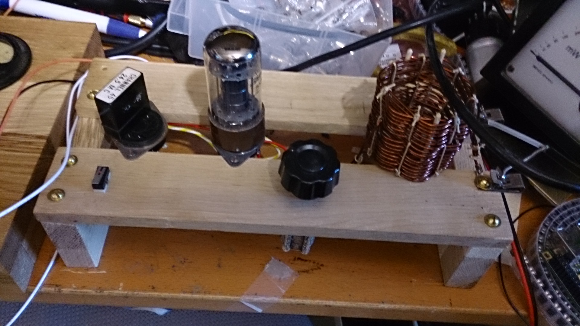
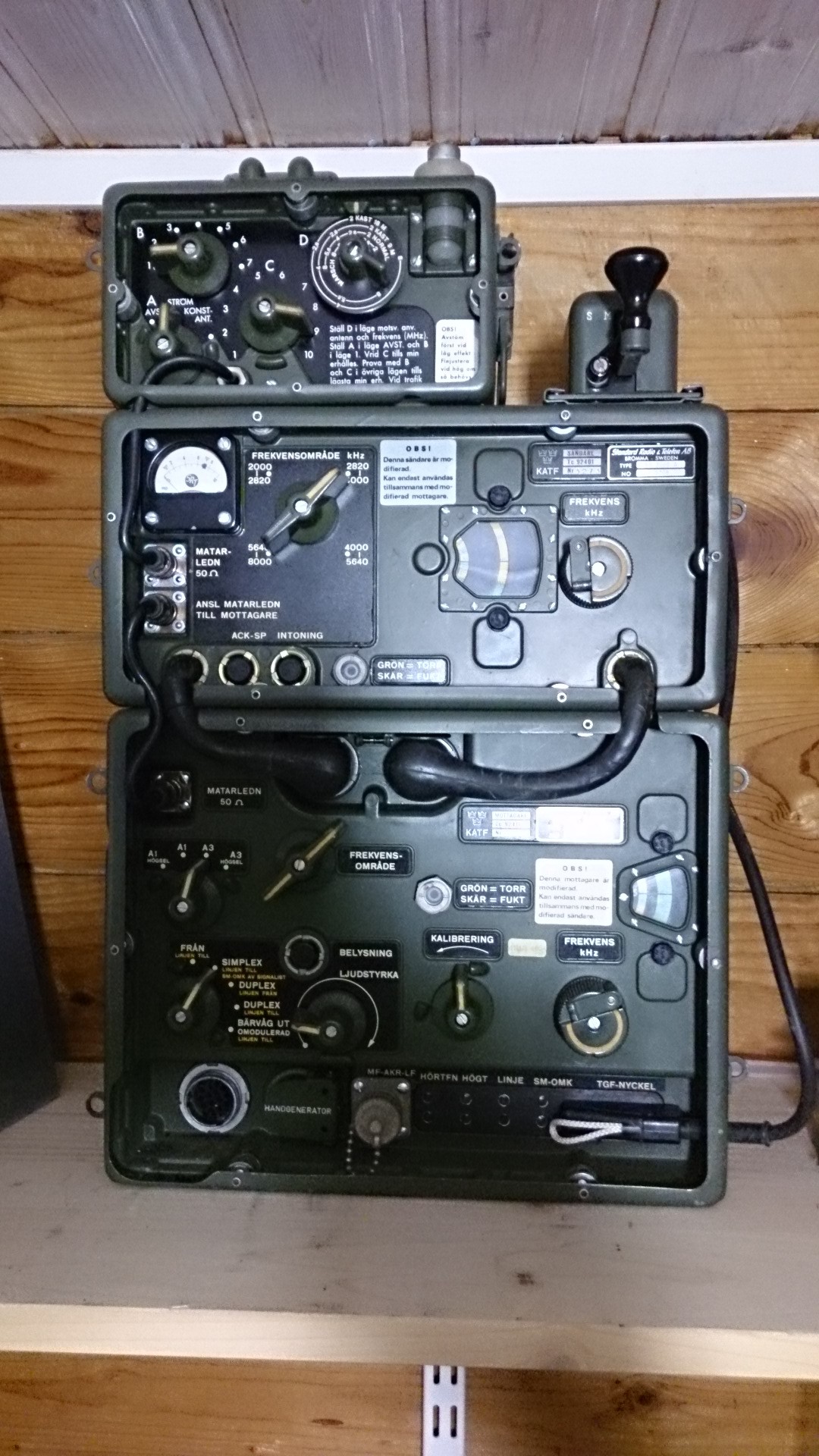
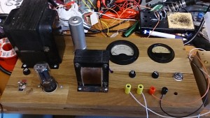
I wouldn’t power the tube transmitter from something silicon based… So once again Johnny had some parts for me and I built this. It gives me about 340V DC at idle which drops to about 280V at 30mA load. Maximum load is 100mA. Seems to work nicely with the transmitter which chirps nicely when the voltage drops. 🙂

2017-04-19 19.37.56Got this from Johnny as well. A nice condition RA200 military radio including (empty) battery box and utility box. I think I got it up and running but I need a better antenna (so far I only have a 2m transmitting antenna and a 0-30MHz active receiving antenna mounted) to test it further. I did receive distant stations with it, though. And the transmitter seems to work too. 🙂

BombJack up and running

I thought I would try porting an existing game implementation to my own board. I found this guy who made an implementation of BombJack, one of my favorite games. It was made using VHDL for a Xilinx FPGA. I don’t know VHDL, never used Xilinx and it was also made to use an external SRAM to “emulate” a lot of the EPROMs in the game, since the FPGA he used did not have enough built-in RAM. Also he added a converter to use a VGA screen, while I want to use an original 15kHz arcade monitor.

Fortunately, VHDL was not that hard to grasp, and the many comments and good coding style in the implementation certainly helped. Also, he had left implementations for all EPROMS for use in internal RAM, only commented out.

I removed all code for emulating EPROMS from SRAM, the SRAM code itself with bootsrapping and stuff. I also removed the VGA converter. I had to change all EPROMS to use the Altera internal RAMs instead.

One big problem was he used a processor core programmed specifically for Xilinx. Luckily I found an Altera port of the exact same processor, and could just swap it.

After some quirks and bug finding it sprung to life!

2016-03-19 00.25.11

At this point it seems to be working flawlessly.

2016-03-19 00.16.23

A big thanks to Alex! Without his implementation and hard work this could never have been made in such short time.

JAMMA board up and running

All tests are ALMOST ok! The only problems found are the P2_RIGHT problem and one of the pins of the big I/O connector don’t have contact with the FPGA pin. Bad solder joints under the FPGA. Not strange in any way. 🙂

So, if everything is ok we should take it for a test drive, right?

I have already cloned Sprint 2 to a modified version of my previous PCB, so I made a copy of that project and in the new one I changed the FPGA type and re-assigned all I/O’s. I also made this connector for the steering wheel giving the optos 3.3V, 0V and gets the pulses pack. Very professional work with the connector there… *cough*

2016-03-12 23.17.37The black connector in the middle with the gray wires. Yes, the one with the perfect solder joints.

And… It works flawlessly! 😀

2016-03-12 23.17.00

Haven’t connected the dip switches in the Sprint project, though… I should do that.

A new JAMMA PCB is born…

After my Pi arcade graphics board I thought I would take it a step further. It would be nice with a JAMMA board with a big FPGA, opto-isolated JAMMA inputs and a lot of I/O to add more functions and devices if needed.

So, I went ahead and designed one. It has the same audio amp as the Pi arcade board, it has 2×8 dip switches, all inputs from the JAMMA is opto isolated and it has one 40-pin and two 16-pin I/O ports. I also added the RAM from the Pi arcade board (512k x 8, 10ns). And the FPGA is a 55k one. Should be enough for many old games and also for many new projects with an added processor (it will probably be 100% compatible with the old Pi arcade board).

It took a few weeks to cad it (on my spare time), there are at least 150 pins for the power supply only… The FPGA has a total of 484 pins.

2016-03-06 21.37.30FPGA mounted together with the other surface mounted components.

2016-03-05 15.55.17…and the back side.

Mounting the FPGA was not easy, and the first attempt failed. However, after re-balling the FPGA with my soldering iron (i didn’t even think that was possible) I got a response on the JTAG chain!

I implemented a character generator in Verilog and started writing tests to read the JAMMA signals. By some reason 2P Right fails, everything else worked. Also the DIPs worked fine.

Yesterday I added a walking-one test for the RAM, and it seems the RAM is working fine as well.

2016-03-10 19.57.47The position of the printouts are messed up, but I think you get the idea. 😉

Today I implemented a sound test but I didn’t test it yet. For now it should output a 1kHz sine wave. I will make it output frequencies from 20Hz up to 20kHz when I get the base going.

Sprint 2 FPGA project

So, I decided it might be fun to squeeze an old video game into an FPGA. I do have my arcade adapter board which has an FPGA plus the needed video DAC and sound amp.

I thought I would try with Sprint 2 as it is a game I saw when I was young (too young to play) but always thought looked cool. Another plus was the small ROM space needed as my arcade board only has a 6k gate FPGA (using about 80% in total for the game).

After a calendar month of work I have learned a lot more about FPGA’s and Verilog, although there is plenty more to learn.

A very nice guy (Cimex on www.arkadtorget.se) supplied me with an actual steering wheel of the game and after making an opto board for it it works like a charm. Still missing a shift stick, but I added shift up and down inputs to the hardware instead, and that is working good for now.

Demo (in Swedish, sorry):

Building a reflow oven

When soldering boards the other day I realized I need a reflow oven. Especially for those hard-to-solder-without-microscope IC’s.

First I looked at some chinese ovens available on Ebay. However, it seemed people had a lot of problems with them. I decided to build my own using a Kickstarter kit. I bought the cheapest oven I could find, ripped it apart and modified it.

2015-09-20 13.08.51My victim!

The kickstarter kit contained a controller, solid state relays, insulation for the oven and a bunch of other stuff needed. Good quality stuff!

2015-09-20 13.47.36Controller

2015-09-24 21.24.04Solid state relays, here mounted in the oven

2015-09-25 20.04.51Insulation and controller in place!

I followed the build guide more or less, jumping a bit back and forth. The result was a well-working oven, at least so far. I made three game PCBs so far, all working flawlessly!

2015-09-26 17.46.27Oven baked game PCB

Ah, I almost forgot… These guys make excellent plastic smt stencils. Working great!

Character test

Yesterday evening I put together the first methods of my character handler. Now all sound files are read (currently about 140) and put in an array which keeps track of what character can say what, and you can then ask for a line read by a randomized character. 🙂 I will make it a little smarter so each line cannot be selected twice in a short time as it is now. Sounds a little empty without music and the rest of the planned sound effects, but it works quite nicely! 🙂

More demo videos

There are some more videos, I might as well put them here as well.

Shadow testing. This worked well….as long as the shadow didn’t move. When I think of it, this idea might not be fully tested, maybe there is one test left… 😉


Actual shmup demo. Animated enemies, animated ship, shooting enemies. Background stolen from another game. 🙂


This is the actual newer-looking shmup we are working on. Zoomed in, that’s why the ship seems a bit big. 😉


Very early video of NASG (Not Another Space Game) video intro.

NASG

NASG (Not Another Space Game) will be a retro-looking shoot-em-up. Plot: Our hero is chased by evil aliens, escaping through a time vortex and is moved back in time. I have limited graphics abilities myself, but I am good enough for this type of game. However, what I would like help with is the character’s voices.

You can record as many variations of each line as you want, the more the better! It will all be used randomly. Most of my variations below has been used, so try to come up with other ones making your character unique!

Recording can be done using your phone. iPhone users can use “Take” and Android users can use “Hi-Q MP3 Voice Recorder” which is free for up to 10min recordings and gives excellent results. Try to be in a quiet room!

These lines are in the plan at the moment:

– Get him! (hunting the hero)
– Hurry up! (hunting the hero)
– Follow him! (hunting the hero)
– What the…? (What..? What the h*ll..? etc) (Questioning, that is. Several versions, please!)
– WHAT!? (Screaming out loud)
– What happened..?
– We’re like sitting ducks here! (alien cannot move much, like in space invaders)
– Nooooo, [insert random alien name here]! (when alien buddy gets shot)
– You bastard! (Shouting at the hero… There are a million variations here… “Your mother is a…” Come up with something fun! The more the better!)
– This is so silly…. (Not happy with how the game works)
– HA! We GOT him! (Hero died)
– No, wait… He’s back. F*ck! (Hero had more lives)
– Fire! (Shoot him! Destroy him! Blast him to the seventies!)
– Seriously…?
– Damn! (F*ck! For Christ’s sake… General swearing)
– Oh noooo…..
– THIS time we WILL get him!
– NOW how do we look…?
– That’s good.
– This is SO strange… (This is sooooo fu**ed up…)
– Hey, we’re all back again!
– Ah, this is better!
– Now we have better guns!
– Same shitty guns…
– I can move better!
– What does this button do…?
– I can’t do this shit. I’ll go and pick the kids up.
– How humiliating!
– Now it sounds better!
– This is great!
– Moahahaaaa! (Manic laughter)
– Where IS he..?
– Here he comes!
– Now we’re talking!
– [Random stupid comment] (“What time is it?” “Hey, I like your pixels. 24bit?” “My mother was an ugly alien, too!”)
– Idiot!
– How did THIS happen?
– Goodbyyyye!
– Better luck next time!
– Yeah!
– Yeah.
– What HE said. (What…. IT said.)
– What is HE doing here??
– You’re in the wrong game, pal!
– Aaaaaaah! (Terrified)
– Game over, man! Game over!


Monitor interface finished

I don’t think I will be adding more functions to the graphics board. It can do what is needed (as far as I know now) so I think I will call it finished. 🙂 At least version 1.0. Maybe, in a few years or so, when better FPGAs are more affordable, I will do a juiced up compatible version. 🙂

A spec on the board can be found here.

Here is a version of the API, which is evolving all the time.


Game programming

The internet is wonderful.

Suddenly they are all around me. They are good at graphics, music, planning, brainstorming… And, just as suddenly, I find myself being a game programmer. 🙂 I will give you a peek preview of the background of the first level. Tim has made a wonderful job!

New arcade PCB

Many good things have happened. 🙂

First the new PCB arrived.

2015-04-20 18.09.30
The JAMMA connector was perfect, the new footprints I made was ok… I soldered the components and gave it a go. Worked fine! I had to modify the sound filter somewhat and I think I’ll do a re-design here, but it worked fine after adding a resistor.

So, sound amp is working, all inputs from joysticks and buttons are working, JAMMA connector is ok, Pi connector is ok, FPGA module works… I got rid of the last known problem in the FPGA and added a few new features. Now, for each bitmap, you can decide on what part of the screen it is visible. And I added the same thing for each sprite. I can now set a window for each sprite in which it is visible. Great for games with more than one area on the screen at once. 🙂

2015-04-21 23.14.02
This is how it looks with all components mounted, except for the 3.5mm audio connector which has not yet arrived.

FPGA audio!

I started yesterday evening to make a…sound board, sort of. A simple sound data buffer in the FPGA (two sprites were lost in action…) and being able to write to the buffer using the SPI interface. Then, if there are any data in the buffer, the FPGA reads the data and outputs it using 8-bit PWM on the very last free pin. I didn’t have much hope about the sound quality, but it turned out to be quite OK using only a simple RC filter directly on the output of the FPGA. The PCB I’m waiting for has a nice, sharp butterworth filter and a local digital buffer, so it should be even better.

The sound is loaded into RAM on the Pi. Seems it happily allocates at least 40M of RAM. 🙂

Seems YouTube even recognized the music and added some ads to punish me. 😉

Arcade monitor, oscilloscope showing the audio output and computer screen showing writes to the FPGA.

PCB finished

Today i finished the new JAMMA-pcb. I will wait until tonight with my order since I usually remember something I have forgotten just after ordering. 😉

The PCB is designed to be connected to a Raspberry Pi 2 or the older model B with 40 pins I/O. All I/O-pins except CS1 is used. This was enough for 2 players each having joystick, 4 buttons and a start button each. Also coin and test are connected. However, you can use the board with any processor or system as long as they use 3.3V (or have level converters) and have a SPI bus.

I have also added sound. If I can get the FPGA doing what i want it will have 8-bit sound PWMed out of the very last free pin. If you want to use the FPGA sound you will loose a sprite (or maybe two, I’m not sure) since it needs a RAM block and at least 2k RAM. The PWM goes on to a double Butterworth filter (about 22kHz) to get rid of the PWM frequency (probably about 350kHz) that should be supressed by about 100dB by the filter. I added a 3.5mm plug to be able to connect to an external amp, or to connect to the on-board amp that follows the volume pot.

LOTS of things added, so I’m pretty sure something is not OK when the boards arrive. But that’s why they are called prototypes… 🙂

Capture

Font handlig and VSync syncing

Today I implemented fonts. Now you can draw a font of any fixed size anywhere on any bitmap. Well, almost. I still have to take care of what happens when you “paint over 511-0”. But I have a solution for that. Since the font I used was 16 pixels wide nothing was affected.

I also added an important thing. Everyone programming anything to do with video understands the importance on being able to wait for VSync. If you sync your sprite-movements with VSync they will move very smooth. I missed this when drawing the PCB so I had to solder a wire instead. The result was really smooth movements of…everything. 🙂

Or…well. In real life it’s real smooth. 😉 Note the layer handling of pacman, ghosts and text.