All tests are ALMOST ok! The only problems found are the P2_RIGHT problem and one of the pins of the big I/O connector don’t have contact with the FPGA pin. Bad solder joints under the FPGA. Not strange in any way. 🙂
So, if everything is ok we should take it for a test drive, right?
I have already cloned Sprint 2 to a modified version of my previous PCB, so I made a copy of that project and in the new one I changed the FPGA type and re-assigned all I/O’s. I also made this connector for the steering wheel giving the optos 3.3V, 0V and gets the pulses pack. Very professional work with the connector there… *cough*
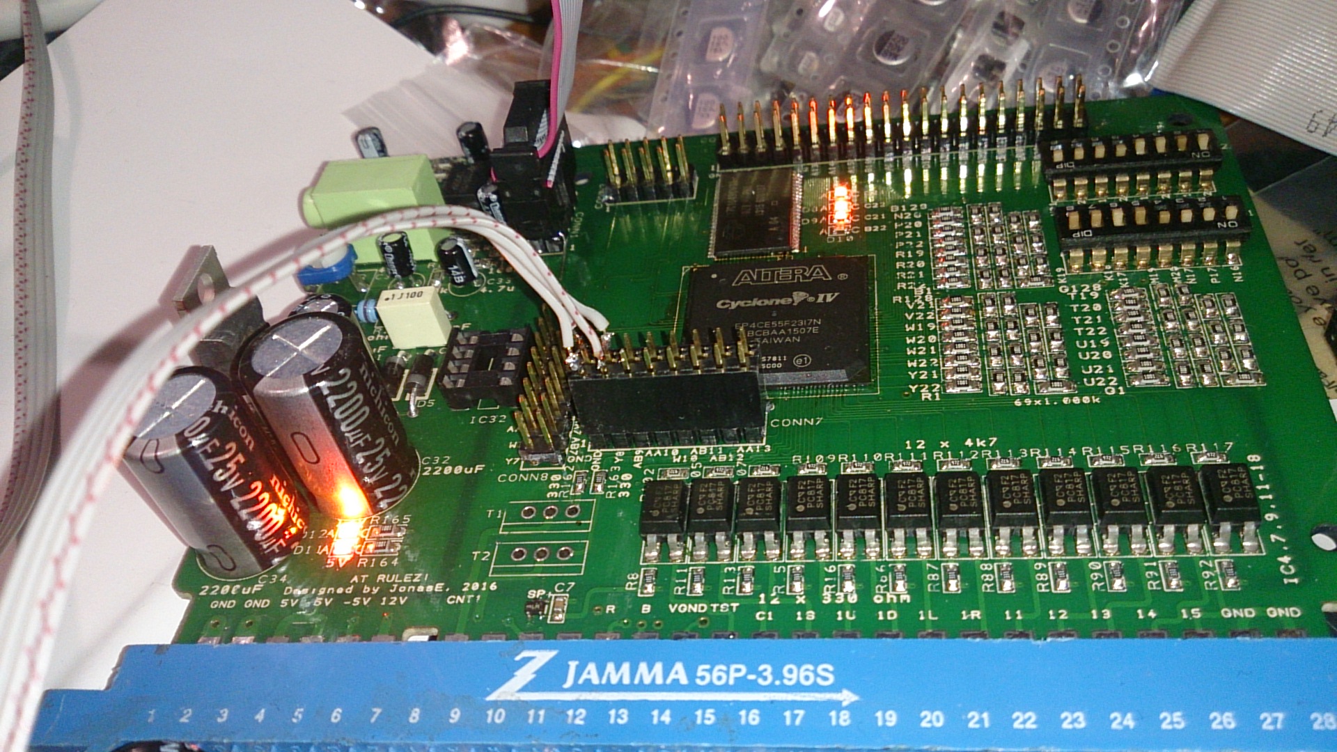 The black connector in the middle with the gray wires. Yes, the one with the perfect solder joints.
And… It works flawlessly! 😀

Haven’t connected the dip switches in the Sprint project, though… I should do that.