New arcade PCB

Many good things have happened. 🙂

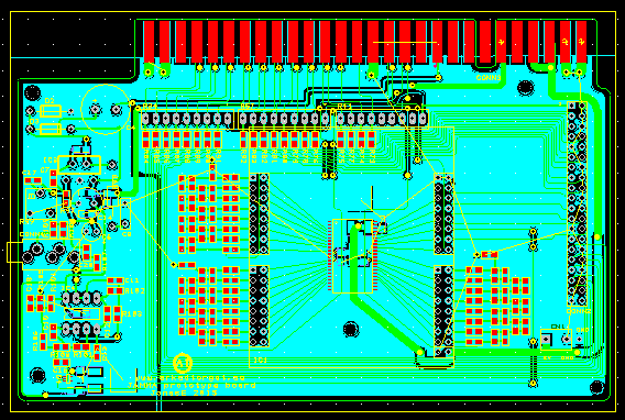
First the new PCB arrived.

2015-04-20 18.09.30
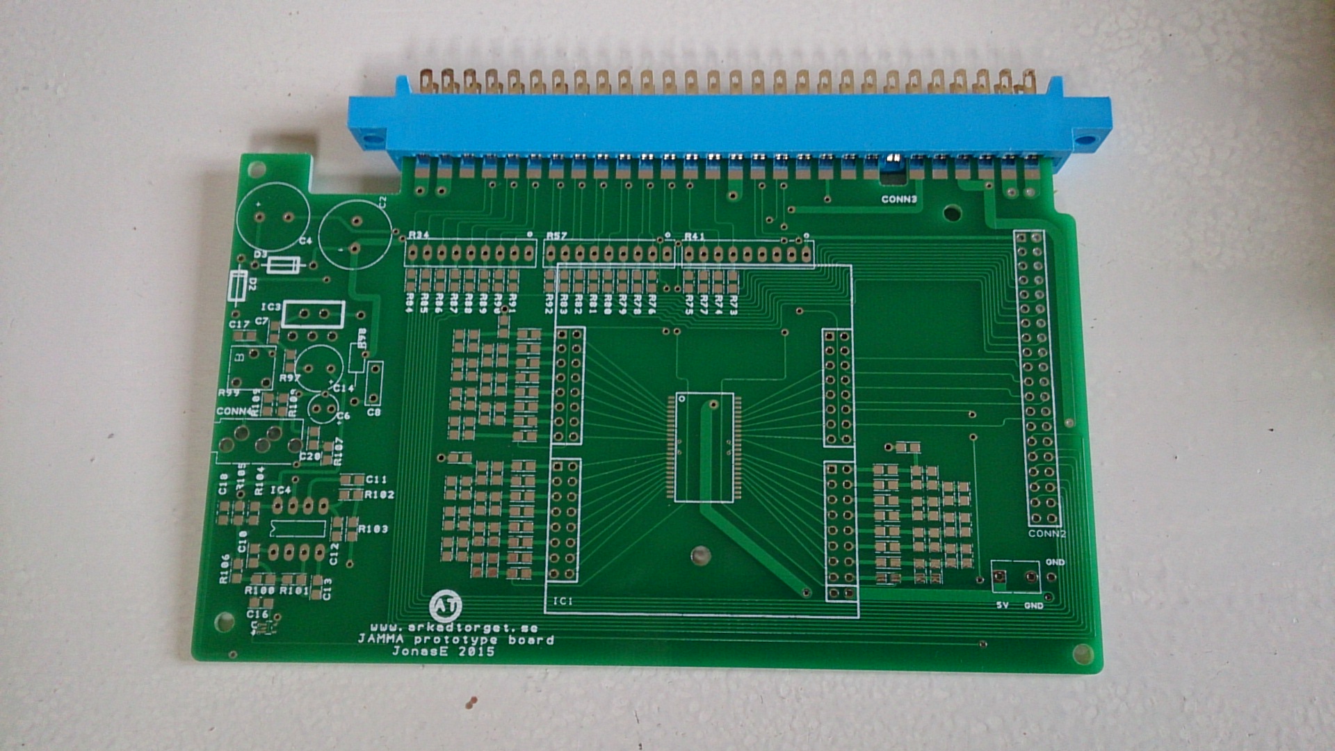
The JAMMA connector was perfect, the new footprints I made was ok… I soldered the components and gave it a go. Worked fine! I had to modify the sound filter somewhat and I think I’ll do a re-design here, but it worked fine after adding a resistor.

So, sound amp is working, all inputs from joysticks and buttons are working, JAMMA connector is ok, Pi connector is ok, FPGA module works… I got rid of the last known problem in the FPGA and added a few new features. Now, for each bitmap, you can decide on what part of the screen it is visible. And I added the same thing for each sprite. I can now set a window for each sprite in which it is visible. Great for games with more than one area on the screen at once. 🙂

2015-04-21 23.14.02
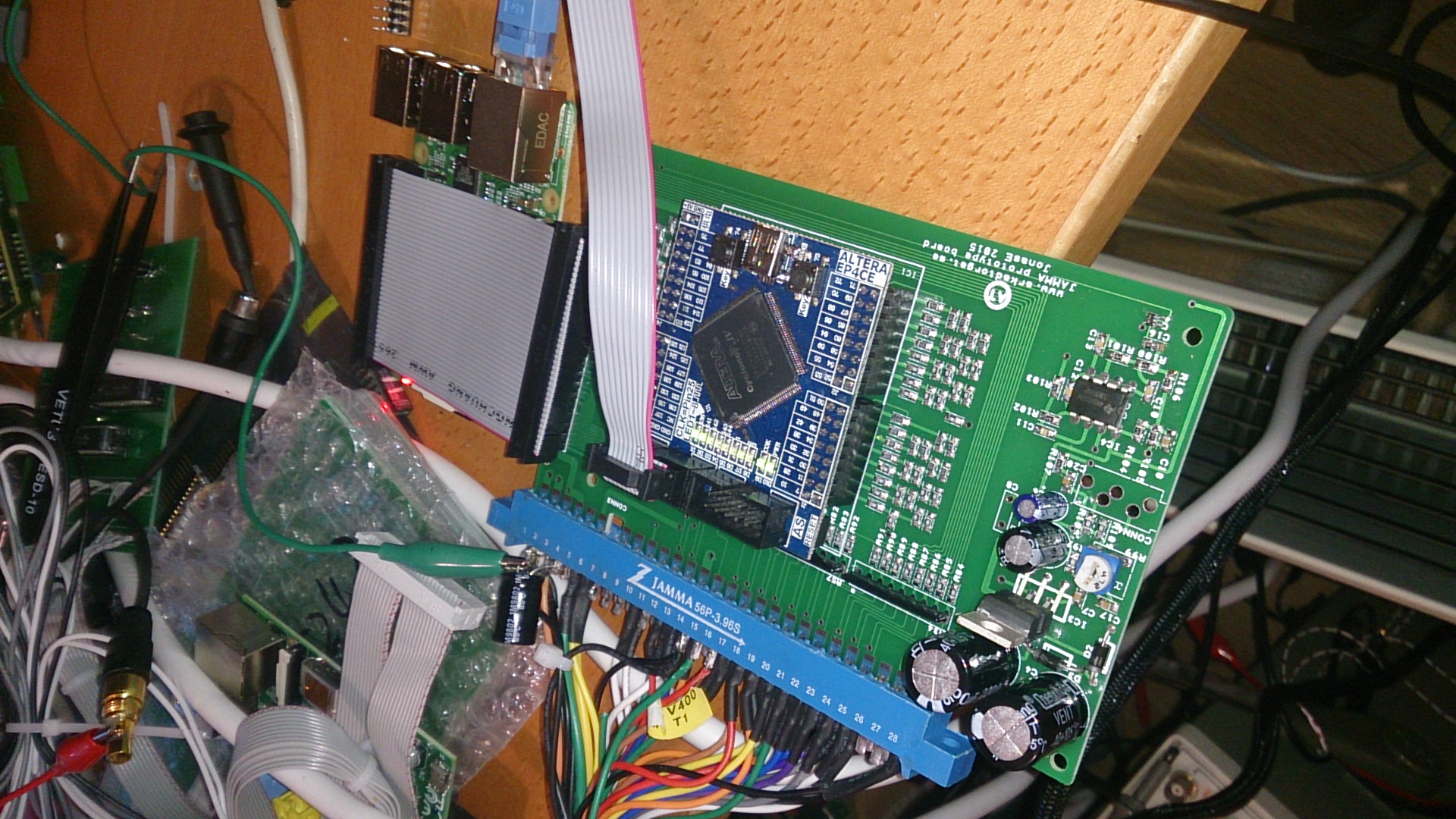
This is how it looks with all components mounted, except for the 3.5mm audio connector which has not yet arrived.

FPGA audio!

I started yesterday evening to make a…sound board, sort of. A simple sound data buffer in the FPGA (two sprites were lost in action…) and being able to write to the buffer using the SPI interface. Then, if there are any data in the buffer, the FPGA reads the data and outputs it using 8-bit PWM on the very last free pin. I didn’t have much hope about the sound quality, but it turned out to be quite OK using only a simple RC filter directly on the output of the FPGA. The PCB I’m waiting for has a nice, sharp butterworth filter and a local digital buffer, so it should be even better.

The sound is loaded into RAM on the Pi. Seems it happily allocates at least 40M of RAM. 🙂

Seems YouTube even recognized the music and added some ads to punish me. 😉

Arcade monitor, oscilloscope showing the audio output and computer screen showing writes to the FPGA.

PCB finished

Today i finished the new JAMMA-pcb. I will wait until tonight with my order since I usually remember something I have forgotten just after ordering. 😉

The PCB is designed to be connected to a Raspberry Pi 2 or the older model B with 40 pins I/O. All I/O-pins except CS1 is used. This was enough for 2 players each having joystick, 4 buttons and a start button each. Also coin and test are connected. However, you can use the board with any processor or system as long as they use 3.3V (or have level converters) and have a SPI bus.

I have also added sound. If I can get the FPGA doing what i want it will have 8-bit sound PWMed out of the very last free pin. If you want to use the FPGA sound you will loose a sprite (or maybe two, I’m not sure) since it needs a RAM block and at least 2k RAM. The PWM goes on to a double Butterworth filter (about 22kHz) to get rid of the PWM frequency (probably about 350kHz) that should be supressed by about 100dB by the filter. I added a 3.5mm plug to be able to connect to an external amp, or to connect to the on-board amp that follows the volume pot.

LOTS of things added, so I’m pretty sure something is not OK when the boards arrive. But that’s why they are called prototypes… 🙂

Capture

Font handlig and VSync syncing

Today I implemented fonts. Now you can draw a font of any fixed size anywhere on any bitmap. Well, almost. I still have to take care of what happens when you “paint over 511-0”. But I have a solution for that. Since the font I used was 16 pixels wide nothing was affected.

I also added an important thing. Everyone programming anything to do with video understands the importance on being able to wait for VSync. If you sync your sprite-movements with VSync they will move very smooth. I missed this when drawing the PCB so I had to solder a wire instead. The result was really smooth movements of…everything. 🙂

Or…well. In real life it’s real smooth. 😉 Note the layer handling of pacman, ghosts and text.