BombJack up and running

I thought I would try porting an existing game implementation to my own board. I found this guy who made an implementation of BombJack, one of my favorite games. It was made using VHDL for a Xilinx FPGA. I don’t know VHDL, never used Xilinx and it was also made to use an external SRAM to “emulate” a lot of the EPROMs in the game, since the FPGA he used did not have enough built-in RAM. Also he added a converter to use a VGA screen, while I want to use an original 15kHz arcade monitor.

Fortunately, VHDL was not that hard to grasp, and the many comments and good coding style in the implementation certainly helped. Also, he had left implementations for all EPROMS for use in internal RAM, only commented out.

I removed all code for emulating EPROMS from SRAM, the SRAM code itself with bootsrapping and stuff. I also removed the VGA converter. I had to change all EPROMS to use the Altera internal RAMs instead.

One big problem was he used a processor core programmed specifically for Xilinx. Luckily I found an Altera port of the exact same processor, and could just swap it.

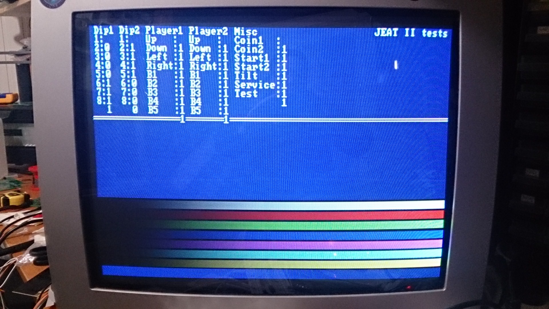
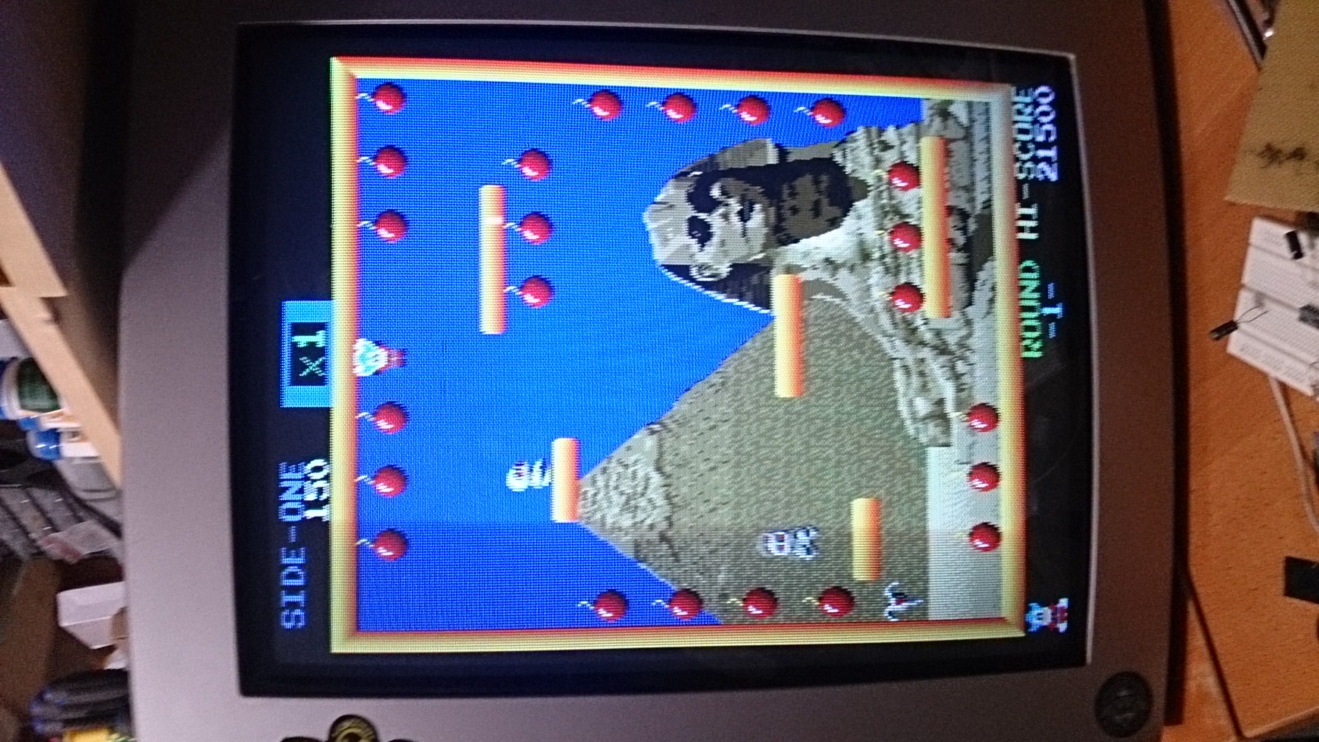
After some quirks and bug finding it sprung to life!

2016-03-19 00.25.11

At this point it seems to be working flawlessly.

2016-03-19 00.16.23

A big thanks to Alex! Without his implementation and hard work this could never have been made in such short time.

JAMMA board up and running

All tests are ALMOST ok! The only problems found are the P2_RIGHT problem and one of the pins of the big I/O connector don’t have contact with the FPGA pin. Bad solder joints under the FPGA. Not strange in any way. 🙂

So, if everything is ok we should take it for a test drive, right?

I have already cloned Sprint 2 to a modified version of my previous PCB, so I made a copy of that project and in the new one I changed the FPGA type and re-assigned all I/O’s. I also made this connector for the steering wheel giving the optos 3.3V, 0V and gets the pulses pack. Very professional work with the connector there… *cough*

2016-03-12 23.17.37The black connector in the middle with the gray wires. Yes, the one with the perfect solder joints.

And… It works flawlessly! 😀

2016-03-12 23.17.00

Haven’t connected the dip switches in the Sprint project, though… I should do that.

A new JAMMA PCB is born…

After my Pi arcade graphics board I thought I would take it a step further. It would be nice with a JAMMA board with a big FPGA, opto-isolated JAMMA inputs and a lot of I/O to add more functions and devices if needed.

So, I went ahead and designed one. It has the same audio amp as the Pi arcade board, it has 2×8 dip switches, all inputs from the JAMMA is opto isolated and it has one 40-pin and two 16-pin I/O ports. I also added the RAM from the Pi arcade board (512k x 8, 10ns). And the FPGA is a 55k one. Should be enough for many old games and also for many new projects with an added processor (it will probably be 100% compatible with the old Pi arcade board).

It took a few weeks to cad it (on my spare time), there are at least 150 pins for the power supply only… The FPGA has a total of 484 pins.

2016-03-06 21.37.30FPGA mounted together with the other surface mounted components.

2016-03-05 15.55.17…and the back side.

Mounting the FPGA was not easy, and the first attempt failed. However, after re-balling the FPGA with my soldering iron (i didn’t even think that was possible) I got a response on the JTAG chain!

I implemented a character generator in Verilog and started writing tests to read the JAMMA signals. By some reason 2P Right fails, everything else worked. Also the DIPs worked fine.

Yesterday I added a walking-one test for the RAM, and it seems the RAM is working fine as well.

2016-03-10 19.57.47The position of the printouts are messed up, but I think you get the idea. 😉

Today I implemented a sound test but I didn’t test it yet. For now it should output a 1kHz sine wave. I will make it output frequencies from 20Hz up to 20kHz when I get the base going.

Sprint 2 FPGA project

So, I decided it might be fun to squeeze an old video game into an FPGA. I do have my arcade adapter board which has an FPGA plus the needed video DAC and sound amp.

I thought I would try with Sprint 2 as it is a game I saw when I was young (too young to play) but always thought looked cool. Another plus was the small ROM space needed as my arcade board only has a 6k gate FPGA (using about 80% in total for the game).

After a calendar month of work I have learned a lot more about FPGA’s and Verilog, although there is plenty more to learn.

A very nice guy (Cimex on www.arkadtorget.se) supplied me with an actual steering wheel of the game and after making an opto board for it it works like a charm. Still missing a shift stick, but I added shift up and down inputs to the hardware instead, and that is working good for now.

Demo (in Swedish, sorry):