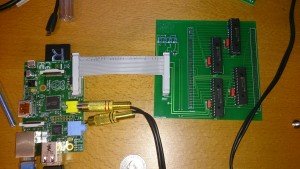
This is a picture of my first I/O-board for the Pi, using I2C.
A simple board using MCP23017. I was planning to use it for debugging arcade boards by connecting it to the processor socket pins. This actually worked better than you may think, but I found a problem with the board. It seemed that if bit 7 of a port changed during some critical passage in the I2C communication (I only had my analogue scope then, so I couldn’t measure it exactly) all port pins was read as “1” by that particular read. I couldn’t find an error in my code or on the PCB (which is not advanced at all) so I asked around on some forums and got another nice guy to test it. And sure enough he found the same error. It all ended with Microchip writing an errata.
Now I needed another I/O-board without these problems. The MC23S17 is the same circuit but uses SPI (which is also quicker, better in my case). This IC does not have the bit 7 issue, and worked flawlessly.
Even if it worked as good as can be expected it was slow in this context, and I could not read and/or write to some devices on the databus due to timing problems. I had to seek another solution for my Z80 debugger. This resulted in the FPGA Z80 pod which has it’s own section, and should be able to emulate read and write cycles of the Z80 flawlessly.
The SPI I/O board will find other uses. My plan is to build a 2532 EPROM programmer using one of them. Even if SPI using MCP23S17 is not very fast compared to direct I/Os (although I tested it up to 10MHz clock speed successfully) it is nice to have boards with a lot of I/Os at hand. The Pi can use SPI clock speeds up to at least 60MHz, and using bigger blocks of data (it can handle 4096 bytes/transfer, it seems) you can actually get some speed. I hope it will be enough for my Pi Arcade monitor interface. See separate section. 🙂
