More demo videos

There are some more videos, I might as well put them here as well.

Shadow testing. This worked well….as long as the shadow didn’t move. When I think of it, this idea might not be fully tested, maybe there is one test left… 😉


Actual shmup demo. Animated enemies, animated ship, shooting enemies. Background stolen from another game. 🙂


This is the actual newer-looking shmup we are working on. Zoomed in, that’s why the ship seems a bit big. 😉


Very early video of NASG (Not Another Space Game) video intro.

Monitor interface finished

I don’t think I will be adding more functions to the graphics board. It can do what is needed (as far as I know now) so I think I will call it finished. 🙂 At least version 1.0. Maybe, in a few years or so, when better FPGAs are more affordable, I will do a juiced up compatible version. 🙂

A spec on the board can be found here.

Here is a version of the API, which is evolving all the time.


Game programming

The internet is wonderful.

Suddenly they are all around me. They are good at graphics, music, planning, brainstorming… And, just as suddenly, I find myself being a game programmer. 🙂 I will give you a peek preview of the background of the first level. Tim has made a wonderful job!

New arcade PCB

Many good things have happened. 🙂

First the new PCB arrived.

2015-04-20 18.09.30
The JAMMA connector was perfect, the new footprints I made was ok… I soldered the components and gave it a go. Worked fine! I had to modify the sound filter somewhat and I think I’ll do a re-design here, but it worked fine after adding a resistor.

So, sound amp is working, all inputs from joysticks and buttons are working, JAMMA connector is ok, Pi connector is ok, FPGA module works… I got rid of the last known problem in the FPGA and added a few new features. Now, for each bitmap, you can decide on what part of the screen it is visible. And I added the same thing for each sprite. I can now set a window for each sprite in which it is visible. Great for games with more than one area on the screen at once. 🙂

2015-04-21 23.14.02
This is how it looks with all components mounted, except for the 3.5mm audio connector which has not yet arrived.

FPGA audio!

I started yesterday evening to make a…sound board, sort of. A simple sound data buffer in the FPGA (two sprites were lost in action…) and being able to write to the buffer using the SPI interface. Then, if there are any data in the buffer, the FPGA reads the data and outputs it using 8-bit PWM on the very last free pin. I didn’t have much hope about the sound quality, but it turned out to be quite OK using only a simple RC filter directly on the output of the FPGA. The PCB I’m waiting for has a nice, sharp butterworth filter and a local digital buffer, so it should be even better.

The sound is loaded into RAM on the Pi. Seems it happily allocates at least 40M of RAM. 🙂

Seems YouTube even recognized the music and added some ads to punish me. 😉

Arcade monitor, oscilloscope showing the audio output and computer screen showing writes to the FPGA.

PCB finished

Today i finished the new JAMMA-pcb. I will wait until tonight with my order since I usually remember something I have forgotten just after ordering. 😉

The PCB is designed to be connected to a Raspberry Pi 2 or the older model B with 40 pins I/O. All I/O-pins except CS1 is used. This was enough for 2 players each having joystick, 4 buttons and a start button each. Also coin and test are connected. However, you can use the board with any processor or system as long as they use 3.3V (or have level converters) and have a SPI bus.

I have also added sound. If I can get the FPGA doing what i want it will have 8-bit sound PWMed out of the very last free pin. If you want to use the FPGA sound you will loose a sprite (or maybe two, I’m not sure) since it needs a RAM block and at least 2k RAM. The PWM goes on to a double Butterworth filter (about 22kHz) to get rid of the PWM frequency (probably about 350kHz) that should be supressed by about 100dB by the filter. I added a 3.5mm plug to be able to connect to an external amp, or to connect to the on-board amp that follows the volume pot.

LOTS of things added, so I’m pretty sure something is not OK when the boards arrive. But that’s why they are called prototypes… 🙂

Capture

Font handlig and VSync syncing

Today I implemented fonts. Now you can draw a font of any fixed size anywhere on any bitmap. Well, almost. I still have to take care of what happens when you “paint over 511-0”. But I have a solution for that. Since the font I used was 16 pixels wide nothing was affected.

I also added an important thing. Everyone programming anything to do with video understands the importance on being able to wait for VSync. If you sync your sprite-movements with VSync they will move very smooth. I missed this when drawing the PCB so I had to solder a wire instead. The result was really smooth movements of…everything. 🙂

Or…well. In real life it’s real smooth. 😉 Note the layer handling of pacman, ghosts and text.


Graphics HW more or less done…

I spent a few hours today trying to come up with a good API for the graphics board. Started good but sort of got messed up after a while. Probably due to hunger. 🙂 I will have to re-think how to handle everything in a good manner.

However, it did result in a graphics test program.

Pacman and his ghosts uses half resolution, i.e one Pacman pixel is 2×2 pixels. Arthur is at his original resolution, but you can hardly see him due to my mobile camera. Also I didn’t get his animation right, it looks like he’s having stomach problems. Also the ghost eyes seems to big, but that is the camera being overexposed or something. Looks fine in real life.

I have also implemented layers for sprites. There are three bitmaps you can play with and each sprite can be in any depth position (under/over/in between).

Sorry again for the crappy video…

So, the HW is fully fit for some serious game programming!

Graphics handling on the way

Ok, after struggling with the SPI a bit (I still have not managed to transfer more than 4096 bytes/transfer) I decided to code around the problem for now.

I implemented a color handler that builds a color table of all sprite shapes and bitmaps needed for a specific “scene”. This seems to work well.

So, tonight, for the first time, I loaded a BMP file with 320×240 pixels and about 80 used colors. Tadaaa! 🙂

2015-03-28 20.49.07

I then loaded a few test sprites which added a few colors more and placed one on a higher layer. And that worked perfectly too, both concerning colors and everything else.

Happiness! 🙂

All ok!

Ah! Now everything seems to work as expected. Sprites look perfect, there are no ghost pixels, I can abuse the SPI as I want without display problems, FPGA is stable… So, tomorrow I will start coding a small demo and extending the API. Let’s hope no more bugs turns up! 🙂

Color working

Color is up and running!

2015-03-23 20.16.24

I had a lot of problems with instability. Sometimes a build worked, I then changed some small detail and it stopped working. The synthesizer says it should work up to 115MHz and I ran it at 100MHz. Should be OK. But when I went down to 90MHz the problems seemed to stop. Now it seems stable.

Just a few strange problems left. When a sprite is half outside the screen to the right some red pixels show up to the left, outside the picture. Should be impossible. Very strange. 🙂 A color seems a bit off on the sprites as well. If you look you can see that the right white stripe on each sprite is thicker than the left one. It should be a black and a white stripe. Not two white. But I don’t see this problem on other sprite shapes. I have to investigate…

After that, if nothing else turns up, it’s time for some serious C and C++ coding to make use of it. 🙂

Sprites seems ok!

After some tinkering I found a nasty bug in the sprite-data-loading-stuff that made the FPGA hang now and then. With that out of the way I looked a bit more at the sprites. They looked sad. 🙂 After some creative clocking/buffering/cheating I finally made them look as they should! 🙂 Let’s hope there are no more lurking bugs in that section now.

2015-03-22 19.21.35

Now, on to colors! 🙂

Sprite work….

Ok, if I want to test the sprites in a good way I have to make it possible to load some graphics from files. I found this tool for drawing sprites, and I made it export my sprites to a .bmp file. I then found the .bmp file format specification and made a class that imports .bmp files and can send the sprite data directly to the RAM on the graphics board. (Note: .bmp files stores lines “upside-down” compared to normal graphics. The line at the bottom is stored first. Strange.)

This is how my sprites should look, a number with a white border:

2015-03-21 20.40.16

And this is how they look:

2015-03-21 20.39.21

So, they are “rotated” one pixel in one direction, and one line seems to be missing in the other. Interesting. 🙂 This means I’ve got plenty of stuff to do tomorrow night. 😉

Animated sprites

Ok. I’m not really sure how this happened. I spent about 3 hours last night coding Verilog. I re-designed the sprite module and I made a whole bunch of new states in the main state machine, most involving a pipeline used to get data at 100MB/s from the RAM. I just made it compile. Today I tested it, and…

…it just sort-of worked! You can see one issue, the bottom rows in the sprites seems to be wrong (these are the first pixels on each sprite on each line, monitor is on it’s side), but as a whole it worked better than I could ever have hoped for. Luck actually strikes sometimes. 🙂

I will try to do some more tests tonight. I have to start writing some C-functions to handle sprites and bitmaps so I can import some real image data. Lines and gray-scale sprites are boring. 🙂

“Sprites” and bitmaps

The potential problem with the address pin was a problem. Not with the PCB, but with the FPGA module. One pin is stuck low. 🙁 Fortunately I had another one. Using that one there were no repeating random pixels! 🙂

Yesterday I worked hard to solve a really strange problem with the graphics. It turned out I just wasn’t finished thinking when I wrote the Verilog code. I tested my theory tonight and…. tadaa! No more strange graphic problems!

“Sprites” are still only white 16×16 pixel squares. These are the next step.

I drew two thick lines on the top bitmap. Behind the top bitmap the sprites are displayed, and behind the sprites there are two more bitmaps with one dark stripe each. Not that visible in the video, you will have to look closely. Also testing the separate X and Y offsets for the bitmaps, as you can see. 😉

Next step is to look at the sprites. After that I have to re-work the design of the main state machine. There are some serious optimizations needed to make this work without issues… When that is done I will add the color decoder.

Arcade Monitor Inteface PCB FINALLY arrived!

After 5 long weeks of waiting it finally arrived today. I even left work half an hour early to get it in my hands as soon as possible. 🙂

Will the RAM fit? Will I be able to solder the RAM? Will the 8-bit R2R ladders work ok? Will it burn?

Itead Studio did a good job as usual.

2015-03-17 18.02.59
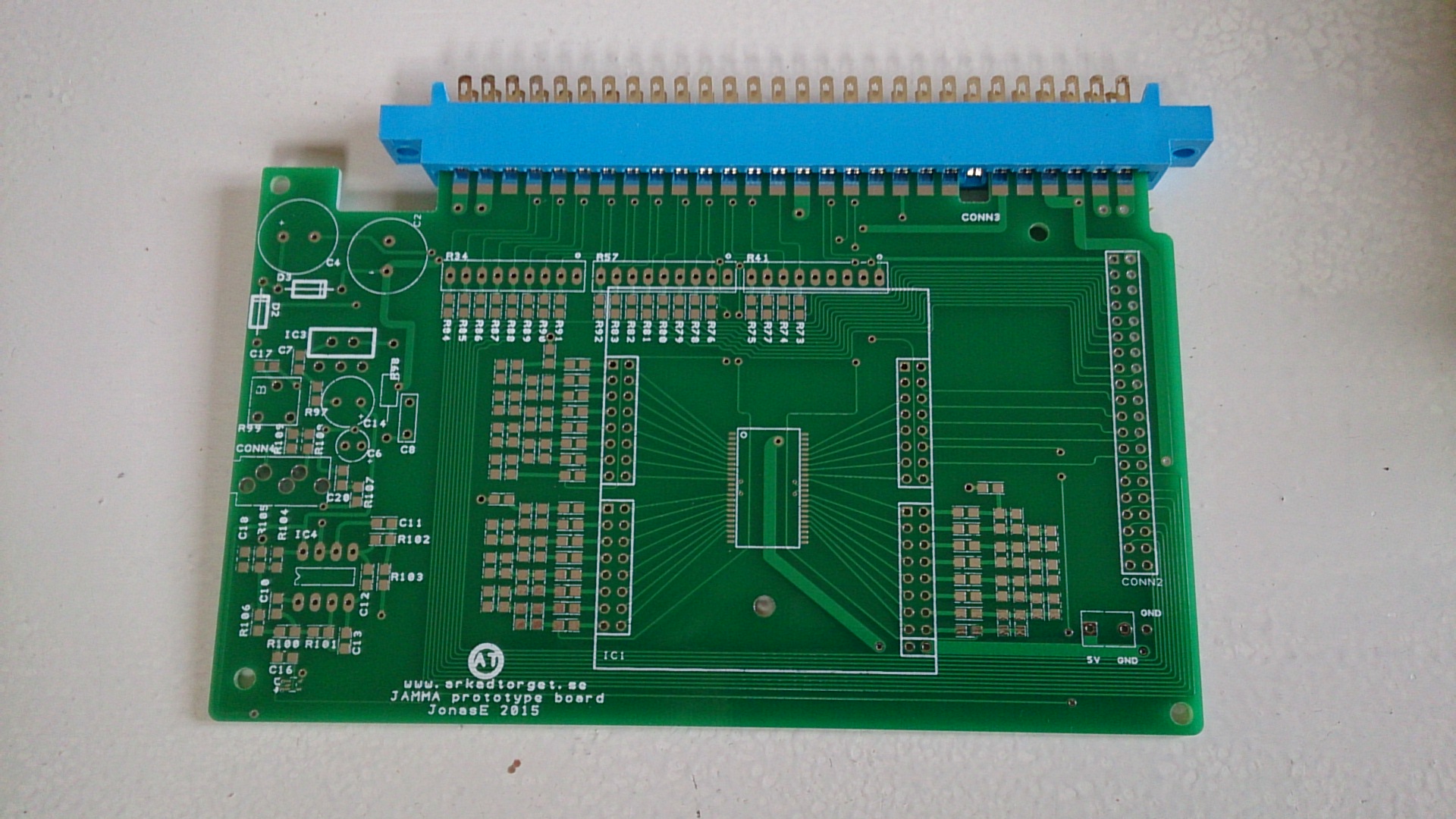
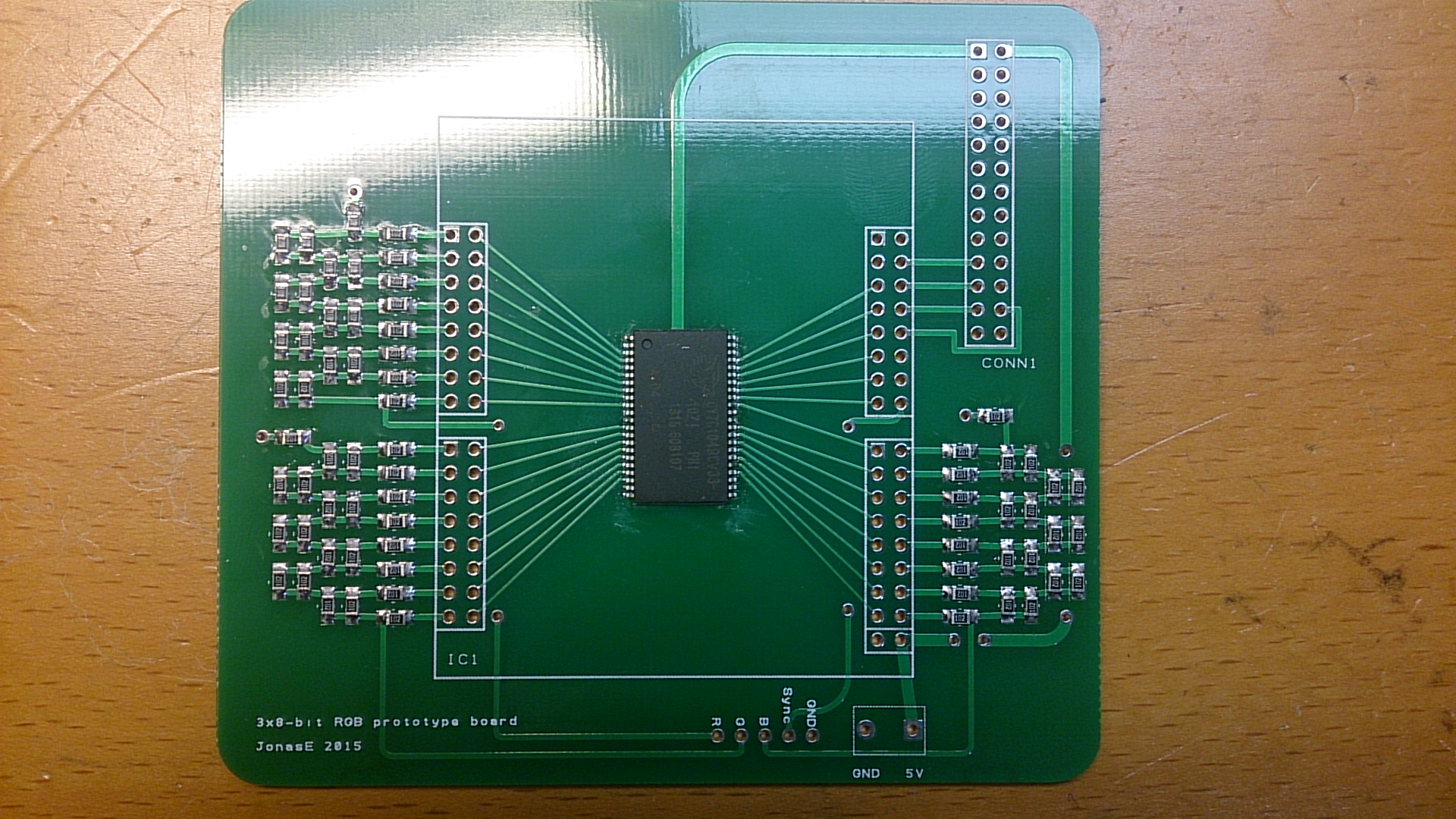
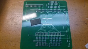
New PCB with RAM IC on top.

Ok, the footprint for the RAM IC was perfect. I wasn’t all all sure it would be as I made the footprint myself. After some tinkering with my solder paste I managed to smear it somewhat even on the pads, and then used my hot-air to solder. Worked good except on some pins that was a bit bent. No problem to fix.

Then I added the resistors for the three 8-bit R2R-ladders.

2015-03-17 18.52.52Resistors added!

This was much quicker than anticipated. All of them (about 75 or so) was soldered in no time at all. I then moved on to the connectors.
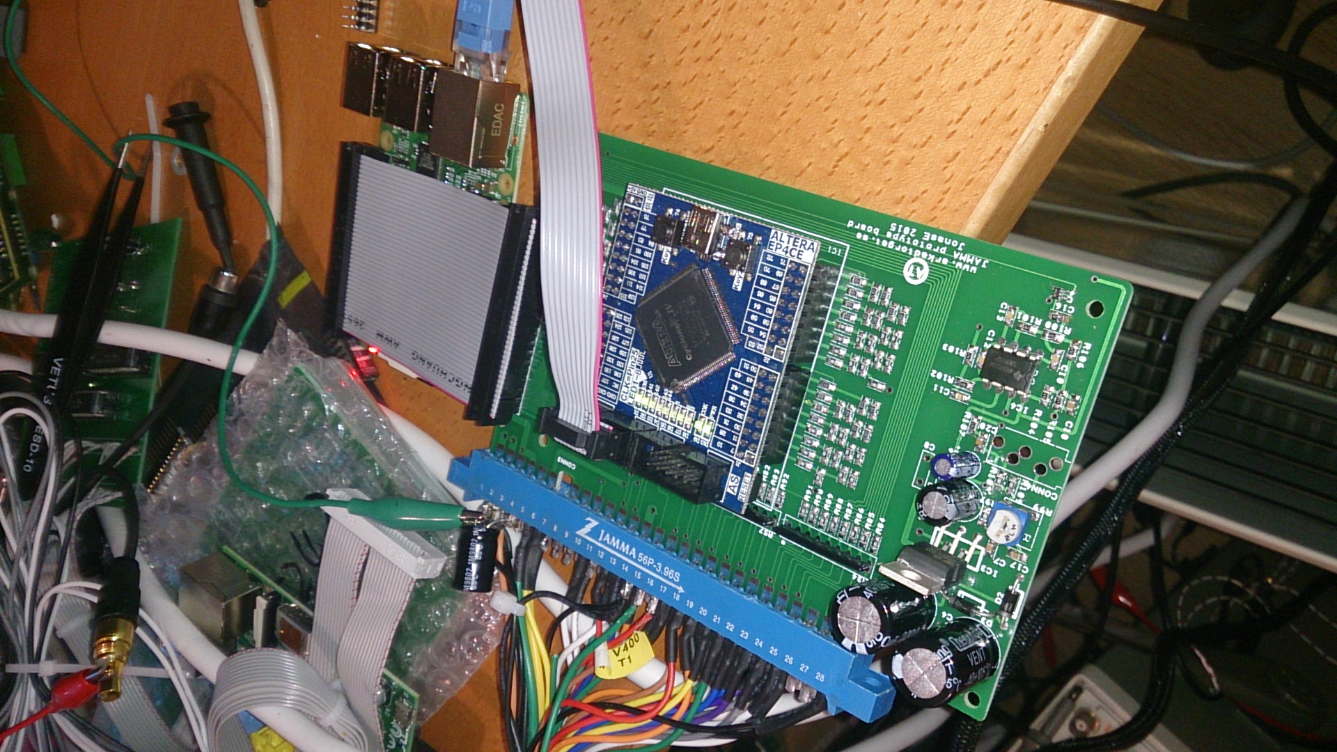
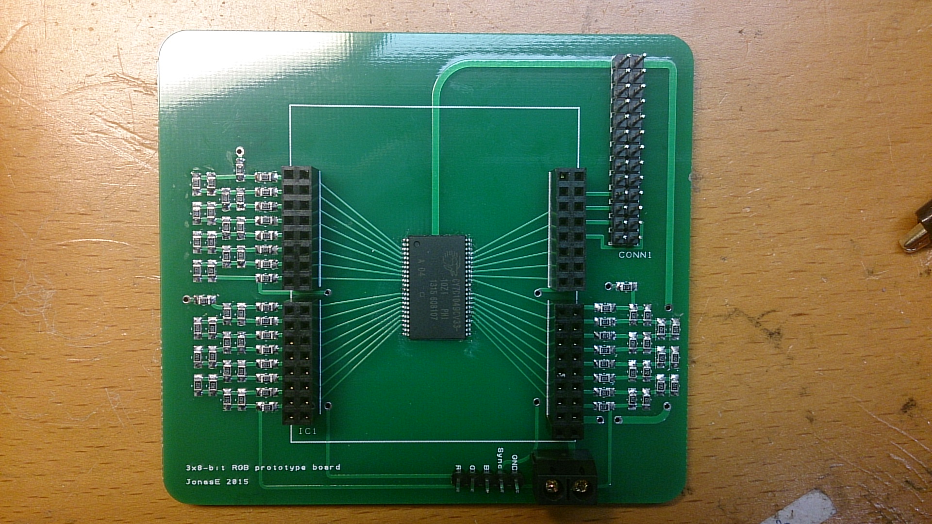
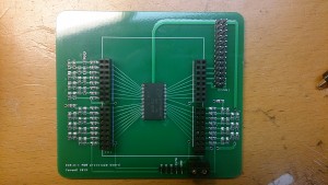
2015-03-17 19.09.25Finished board!

Ok, time to power it up! Will there be smoke?

2015-03-17 19.41.12
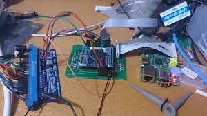
All connected, running on 5V from the Jamma connector and feeding RGB + sync back.

At first there was no working sync. I examined the board and found that I made some sort of mistake. The sync signal was not on the correct pin on the FPGA. A quick swap in the FPGA code and… voila!

2015-03-17 19.41.33
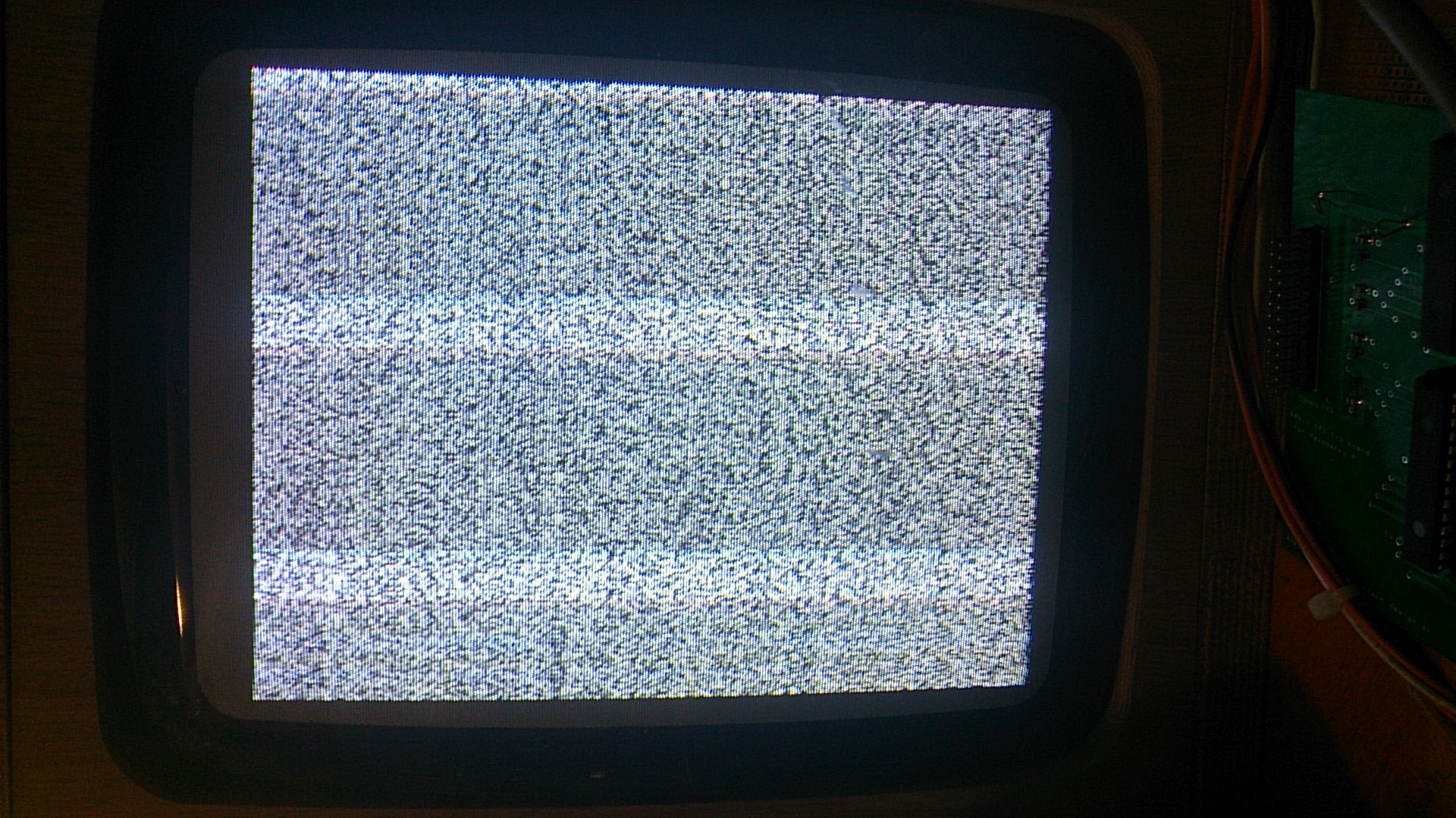
Taking photos of a CRT with a mobile phone camera is not easy… There are no stripes in real life!

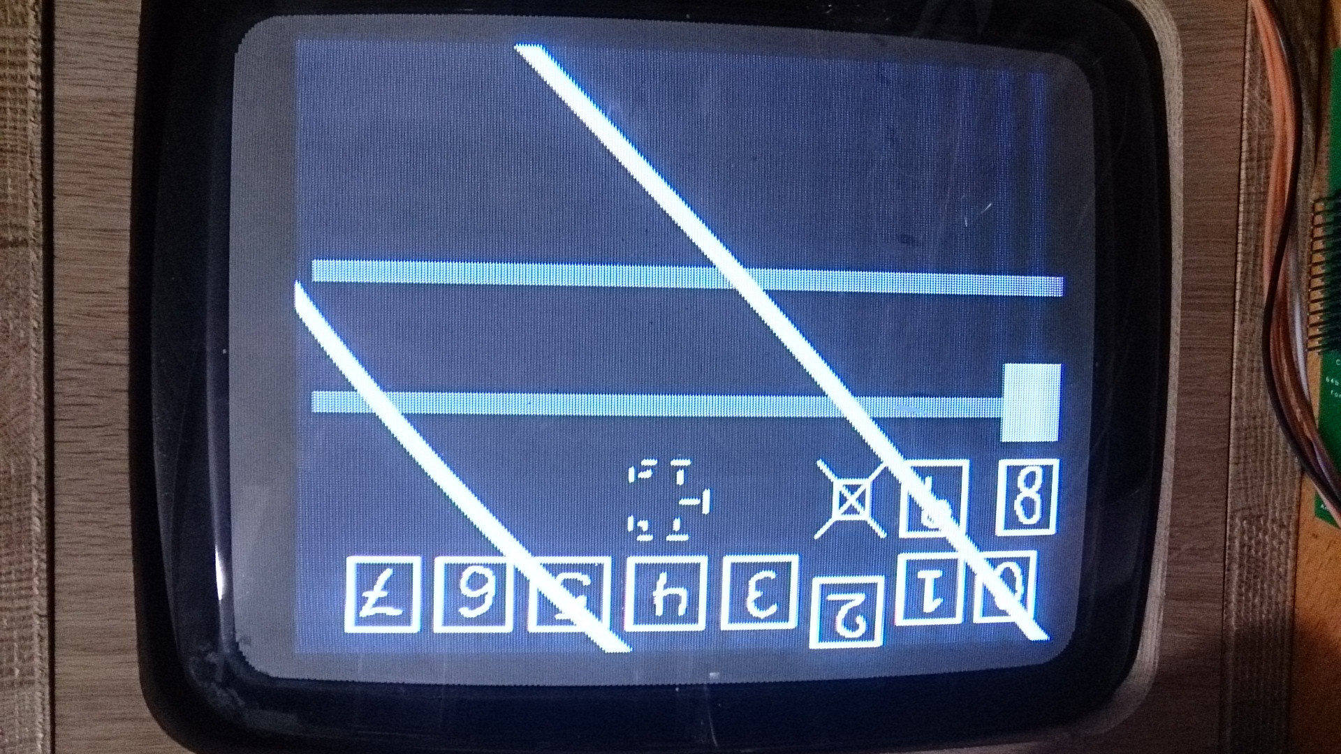
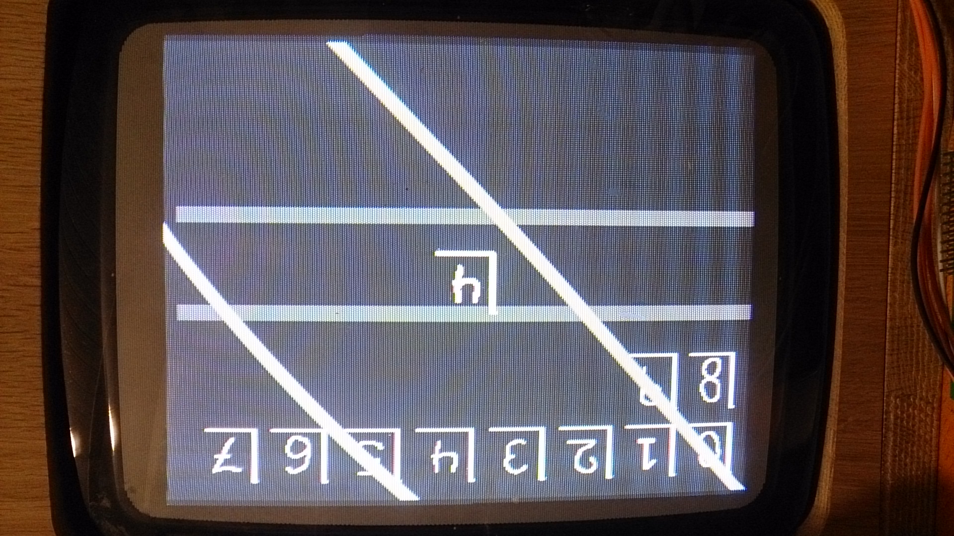
Random pixels! Beautiful! This is the contents in the RAM after powerup. At least it seems to read RAM as it should. Or…. There actually seems there might be a problem, I see some repeating patterns in the random pixels. Might be a stuck address pin. We’ll see later. The picture is perfectly still, no changing pixels or anything. Promising.

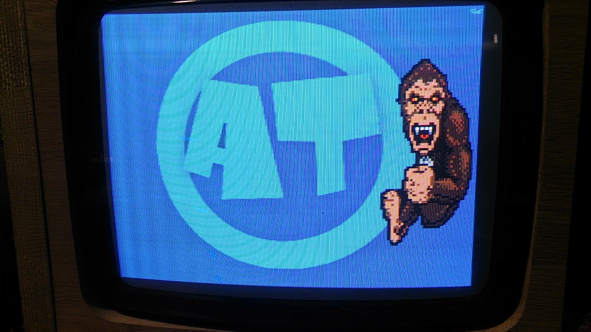
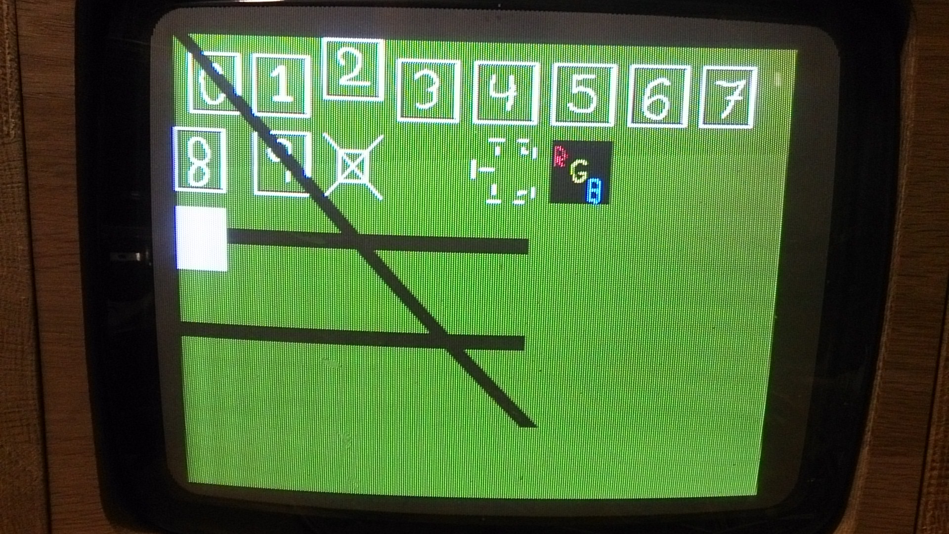
What happens if I press the test picture button?

2015-03-17 19.41.58

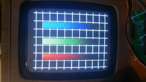
Ah! Totally PERFECT shades of 8-bit RGB. The picture does not do it justice. It really looks awesome! This means you can get away with generating 24-bit video directly from output pins from a FPGA using R2R ladders with a really good result. You need 0.1% resistors, but still! This result is much better than I dared to hope for. So far this is a total success. Now I will move on to some tests using the SPI to write to the RAM. I expect to find some problems here since I see a repeated pattern… See next post for results.


SPI transfer size

Hm, accordning to http://www.raspberrypi.org/forums/viewtopic.php?p=309582 it is possible to extend the amount of maximum sent data of the SPI bus! This is most interesting. This means I should be able to transfer a full framebuffer in one single transfer. Using 352×288 i might be able to do a full frame 30Hz update. If I succeed in increasing the SPI reception in the FPGA to 60Mbit I, in theory, can reach 60Hz.

This is not what it was intended for, but…. Still good to have some power in the SPI.

More work on sprites

I added some more functionality to the sprite module. Instead of writing to the registers that control X, Y, shape and visibility directly, I added buffer registers to hold the written data until the next frame starts. This should give glitch-free update of sprites no matter how you send the data. And it certainly shows on the moving demo. Perfect squares all the way! 🙂

Sorry, no pictures or demos today!

SPI communication up!

After some troublesome debugging I finally got the SPI up and running. I can now move one of the bitmap displayed from RAM (I don’t have a RAM yet, I connected some address wire to one of the D inputs to test. This gives a nice, striped image) in X and Y. 🙂 Also, the FPGA seemed to “crash” in some way before giving me a black image after some random time. That seems to have vanished with the last bug too.

Can’t wait to get my hands on the PCB…. Hopefully it’s made in China as I type this. 🙂