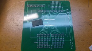
After 5 long weeks of waiting it finally arrived today. I even left work half an hour early to get it in my hands as soon as possible. 🙂
Will the RAM fit? Will I be able to solder the RAM? Will the 8-bit R2R ladders work ok? Will it burn?
Itead Studio did a good job as usual.
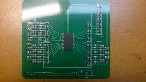
Ok, the footprint for the RAM IC was perfect. I wasn’t all all sure it would be as I made the footprint myself. After some tinkering with my solder paste I managed to smear it somewhat even on the pads, and then used my hot-air to solder. Worked good except on some pins that was a bit bent. No problem to fix.
Then I added the resistors for the three 8-bit R2R-ladders.
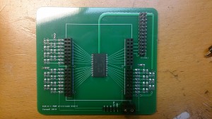
This was much quicker than anticipated. All of them (about 75 or so) was soldered in no time at all. I then moved on to the connectors.
Ok, time to power it up! Will there be smoke?
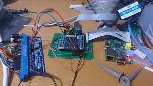 All connected, running on 5V from the Jamma connector and feeding RGB + sync back.
At first there was no working sync. I examined the board and found that I made some sort of mistake. The sync signal was not on the correct pin on the FPGA. A quick swap in the FPGA code and… voila!
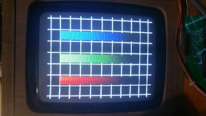
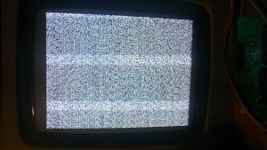 Taking photos of a CRT with a mobile phone camera is not easy… There are no stripes in real life!
Random pixels! Beautiful! This is the contents in the RAM after powerup. At least it seems to read RAM as it should. Or…. There actually seems there might be a problem, I see some repeating patterns in the random pixels. Might be a stuck address pin. We’ll see later. The picture is perfectly still, no changing pixels or anything. Promising.
What happens if I press the test picture button?
Ah! Totally PERFECT shades of 8-bit RGB. The picture does not do it justice. It really looks awesome! This means you can get away with generating 24-bit video directly from output pins from a FPGA using R2R ladders with a really good result. You need 0.1% resistors, but still! This result is much better than I dared to hope for. So far this is a total success. Now I will move on to some tests using the SPI to write to the RAM. I expect to find some problems here since I see a repeated pattern… See next post for results.
