After my Pi arcade graphics board I thought I would take it a step further. It would be nice with a JAMMA board with a big FPGA, opto-isolated JAMMA inputs and a lot of I/O to add more functions and devices if needed.
So, I went ahead and designed one. It has the same audio amp as the Pi arcade board, it has 2×8 dip switches, all inputs from the JAMMA is opto isolated and it has one 40-pin and two 16-pin I/O ports. I also added the RAM from the Pi arcade board (512k x 8, 10ns). And the FPGA is a 55k one. Should be enough for many old games and also for many new projects with an added processor (it will probably be 100% compatible with the old Pi arcade board).
It took a few weeks to cad it (on my spare time), there are at least 150 pins for the power supply only… The FPGA has a total of 484 pins.
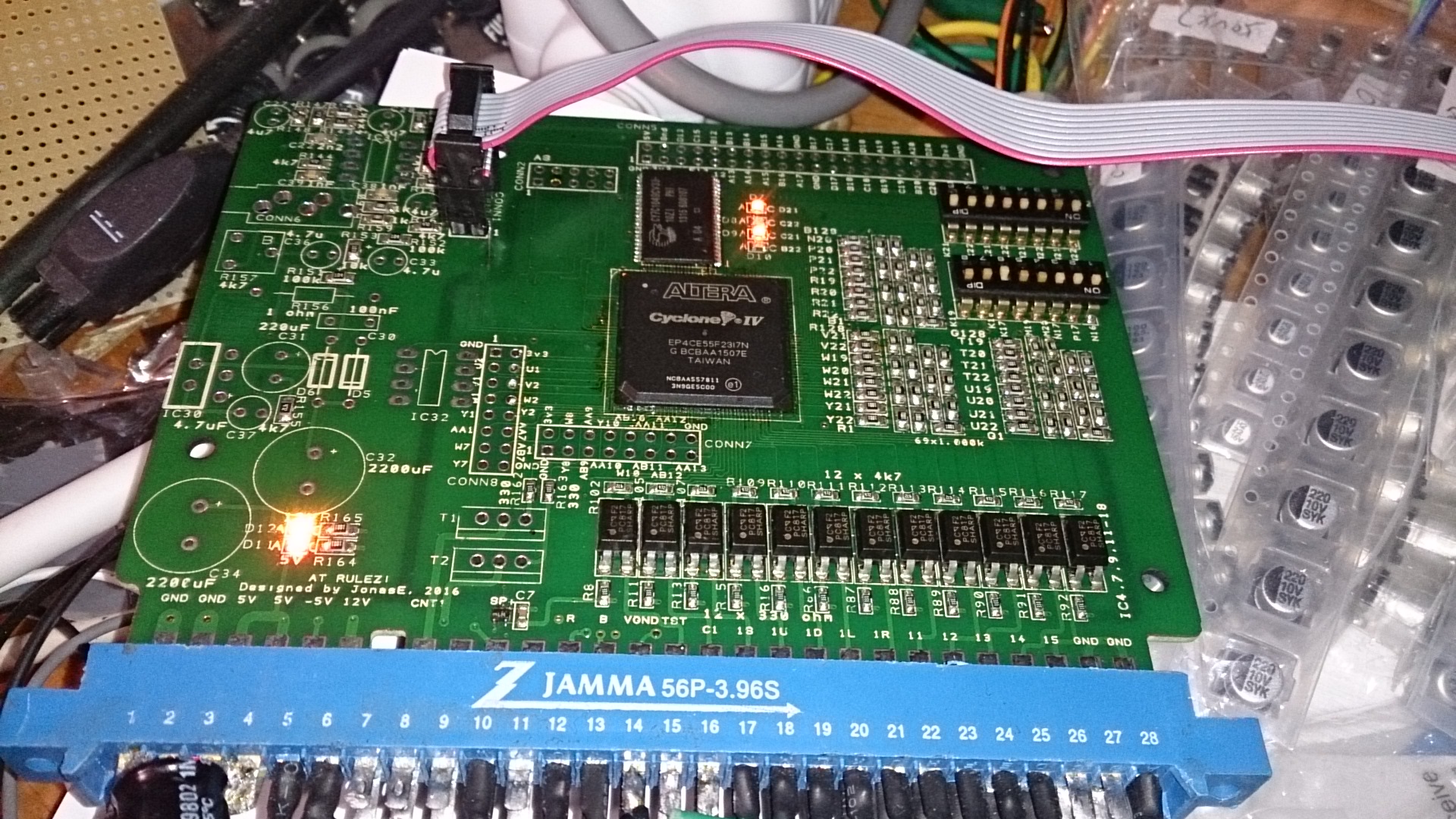 FPGA mounted together with the other surface mounted components.
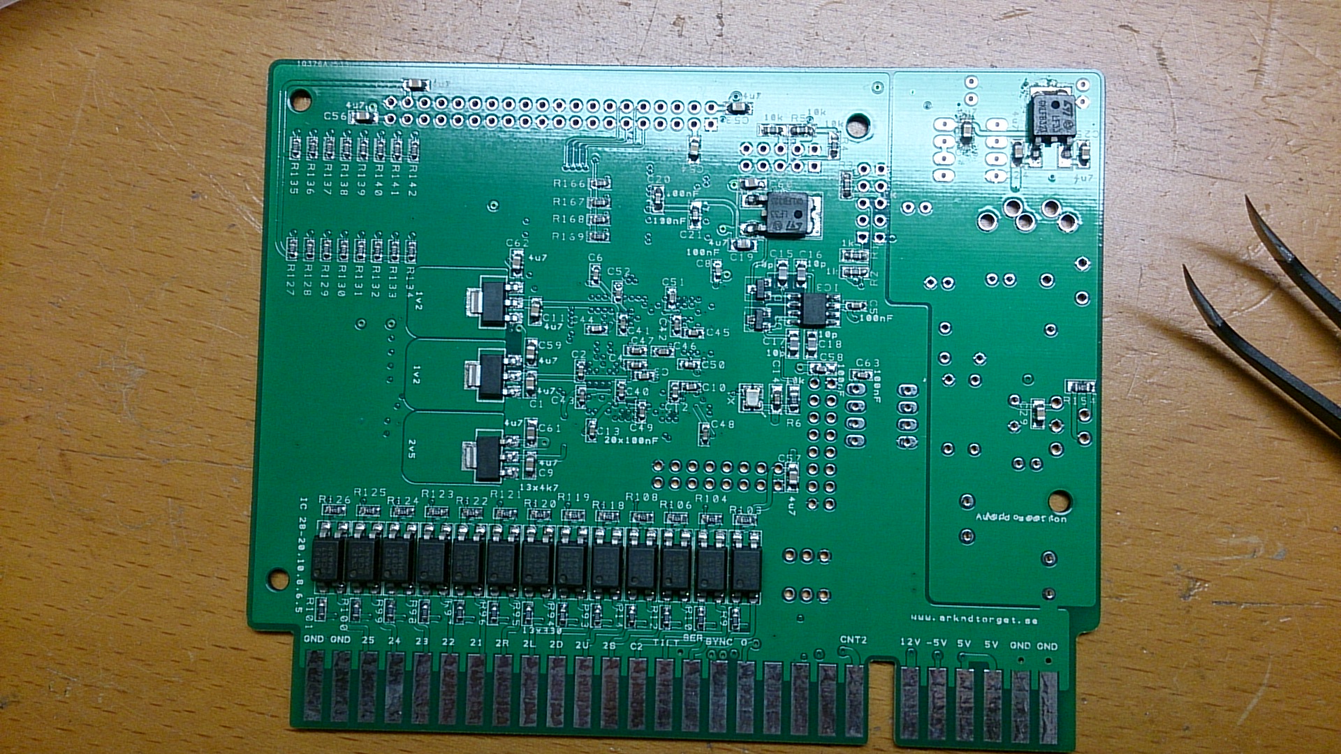 …and the back side.
Mounting the FPGA was not easy, and the first attempt failed. However, after re-balling the FPGA with my soldering iron (i didn’t even think that was possible) I got a response on the JTAG chain!
I implemented a character generator in Verilog and started writing tests to read the JAMMA signals. By some reason 2P Right fails, everything else worked. Also the DIPs worked fine.
Yesterday I added a walking-one test for the RAM, and it seems the RAM is working fine as well.
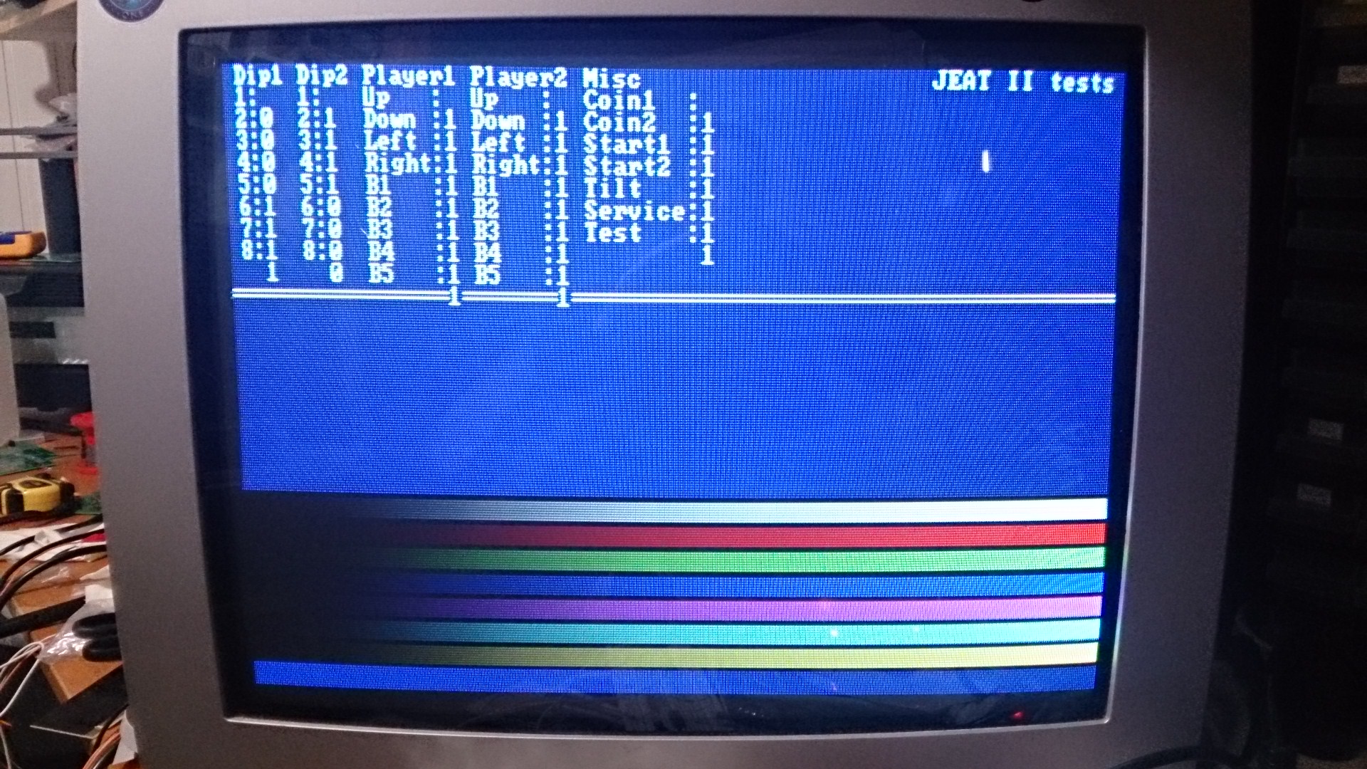 The position of the printouts are messed up, but I think you get the idea. 😉
Today I implemented a sound test but I didn’t test it yet. For now it should output a 1kHz sine wave. I will make it output frequencies from 20Hz up to 20kHz when I get the base going.